Tag: atx

  • PC Case: Physical Design

    For the case design, I started with the basic wall structure, consisting of four fixed walls (top, bottom, front, back) and two removable side panels (left and right), as is typical for PC cases, as well as a central dividing wall, which would hold the motherboard later. As planned, the top, front, and left sides would be made of clear acrylic, with black acrylic used for the others.

    I chose a case size of 50 x 50 x 27 cm, which was quite large for a PC case, but I had the space for it and really didn’t want it to end up cramped. The width was mostly dictated by wanting to have enough cable management space in the back, as well as comfortably fitting a vertically mounted GPU on the left side.

    The edges between walls were covered with corner profiles (made of plastic and aluminium), which also served as the “rails” holding the side panels.
    The placement of the power supply and HDD cage were easy too, so I placed them down right away.

    The power supply got a corresponding cutout in the back, with mounting holes allowing it to be placed with the fan facing up or down. For downwards fan placement, I also added a matching cutout in the bottom panel.
    You can also see here how I added a kind of box joint at the intersections between fixed walls, allowing for a stronger bond between them later.

    With the mock-ups for the motherboard and vertical GPU added, I now had a baseline for designing the rear I/O panels, which would be sheet metal parts designed according to the ATX and PCIe standard requirements, as discussed in the previous chapter.
    The empty space on the main I/O panel was filled with a hexagon hole pattern, to allow at least a little bit of airflow into and out of the case.

    Additionally, I added the lower “shelf” you can see inside the case – this would serve as a mount for the vertical GPU, but also as an aesthetic cover for the HDD cage, power supply, and corresponding cables.

    Looking at the empty space on the bottom of the front panel gave me my first idea for an aesthetic lighting feature: An engraved design and logo in the transparent panel, with LED edge lighting from below.

    The positions of all the main PC components were fixed at this point, so I could start designing the cooling loop.
    As stated in the introduction post, I wanted an external radiator, placed out of sight – same for the coolant pump. Therefore, the case itself would only contain the CPU and GPU cooling blocks, a reservoir, and coolant tubing (some of which would be replaced by channels integrated into the front and top walls).
    To connect it to the external components, I added two quick-disconnect fittings on the back.

    Next, it was time for some more aesthetic LED features – a hexagon accent and logo made of translucent acrylic, an LED bar behind the reservoir, as well as a few more engraved edge-lit features in the left wall.
    Also, you can see that I added some cutouts in the dividing wall around the motherboard, for routing cables.

    Another important part of any PC case is the front panel, which provides the power and reset buttons, the disk activity indicator, and connectors for USB and audio.
    Here’s the design I came up with, on the top right of the case.

    Behind the right panel, the design looked like this. Lots of cutouts and space for cable routing, access to the HDD cage, some 2.5″ SSD mounting spots, small acrylic “shelves” for the front panel electronics, and three circuit boards (logo LEDs, front panel, and case controller), which I will go into in the next chapter.

    At this point, there were just a few details left to add – for example, rubber feet to support the case (while leaving an air gap for the power supply), as well as small rotatable pieces on the back side to lock the side panels into place.

    With that, the basic physical design of the case was complete, and I loved how it turned out.

    For the external cooling components, I found some simple square shelves, into which I could integrate a large square radiator (an Alphacool 480/560mm unit), a small additional reservoir, a drain port for emptying the loop, a flow and temperature sensor (Aquacomputer high flow 2), as well as a sound-dampened box for the coolant pump (initially designed for the Jingway DP1200PWM).

    Placing the case on top of the shelf and connecting the external components resulted in a nice-looking overall system, with most of the “visually unpleasant” components hidden away.

    Physical design done, let’s look at the electronics design next.

  • PC Case: Standards and Materials

    As the main goal of this project was to house PC components and be a functional case for them, the design process was a little different from my usual project designs: Here, I had to follow certain standards (mainly the ATX and PCIe standards) in order to make standard PC components fit inside and have their connectors be accessible on the outside.

    Therefore, I’d have to start with a significant amount of planning in CAD – starting with the central PC component, the motherboard.
    I created a Fusion 360 mock-up of a simplified motherboard, with its mounting holes, I/O shield, and PCIe expansion cards based on the standard specifications.
    This would allow me to easily transfer sizes and positions from this mock-up to my case design, ensuring the case fits all standard specifications.

    I made similar mock-up designs of a standard ATX power supply, a stand-alone PCIe card, and an HDD cage (which I salvaged from an old PC case).

    Because of the design of the motherboard and expansion card I/O panels, I knew that the corresponding case wall would likely have to be made of sheet metal, as is typical in most PC cases: It needs to be quite strong (as it holds the cards, for example) and thin (to not get in the way of connectors).

    My first idea was to build a majority of the case out of sheet metal, with some other material for the transparent walls – however, I quickly discovered that single-quantity custom sheet metal parts are quite expensive, so using them for most of the case would blow up the project cost beyond any reasonable budget.

    Therefore, I decided to keep the sheet metal parts to a minimum (rear I/O only) and switch to a different material for the rest of the case: Laser-cut acrylic plastic.
    While plastic isn’t perfect for PC cases (no EMI shielding, not fire/heat resistant, thermally insulating), it allows the project to be much more affordable, while being visually pleasing and solving the question about transparent wall materials.

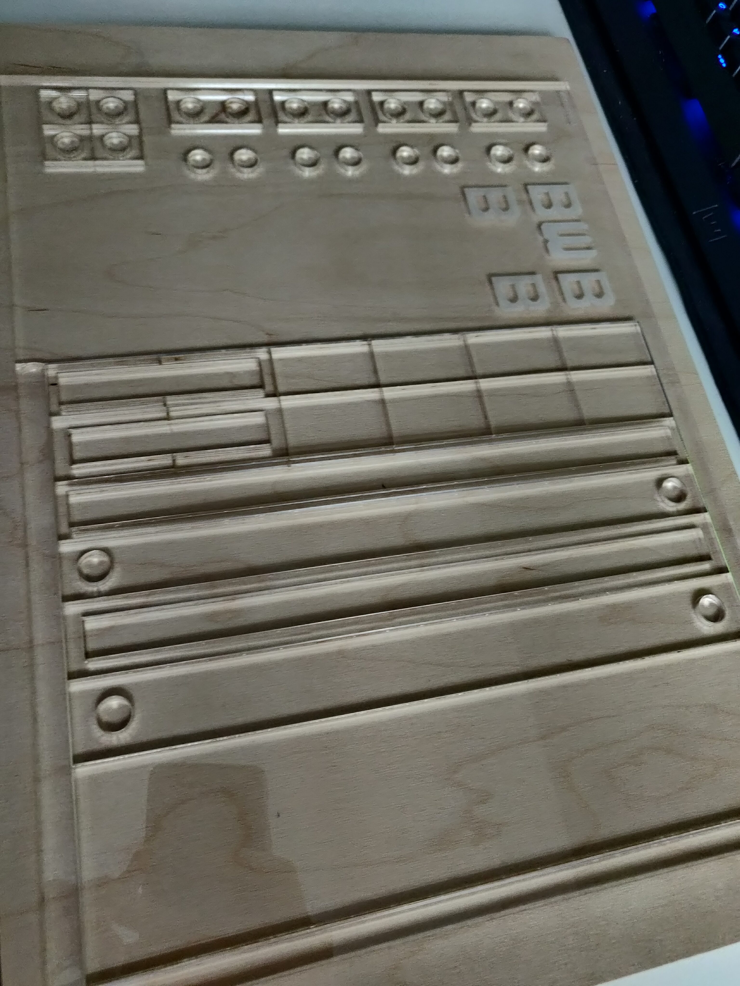
    I had two more ideas that would be fun with acrylic plastic, but they would need to be tested first: Laser engravings (for lighting and visuals), as well as building coolant channels into the transparent side walls of the case.
    So before continuing my design, I ordered some test pieces to be laser cut out of transparent acrylic.

    The first thing I wanted to see was the quality of the engraving, as well as what different engraving options (offered by Sculpteo, the laser cutting company I chose) would look like in real life.

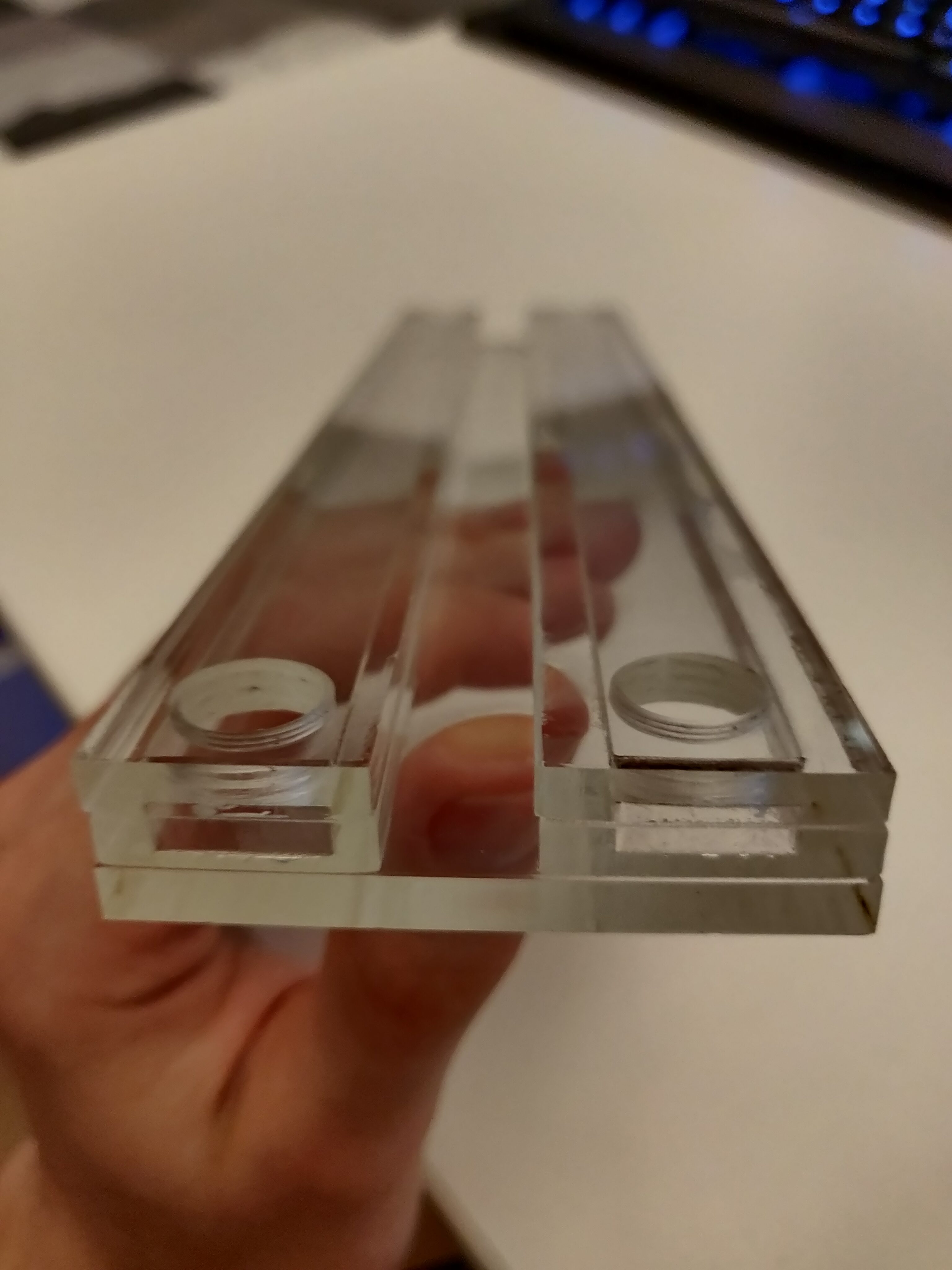
    For testing the idea of integrated coolant channels, I had to test two things: Whether I could glue acrylic layers together sufficiently well for that, and whether I could tap threads for fittings into the acrylic pieces.
    Threads turned out to be quite easy using a corresponding tap, assuming the hole size was chosen well.

    Gluing acrylic layers together was much more difficult. I tried a special glue called Acrifix, but I didn’t like how it behaved for small parts (especially hollow ones), and also it had an extremely unpleasant smell, making it very annoying to work with.
    Another method I found online was solvent bonding using DCM (dichloromethane), basically dissolving a bit of the plastic at the boundary between two pieces, welding them together – so that’s what I tried next.

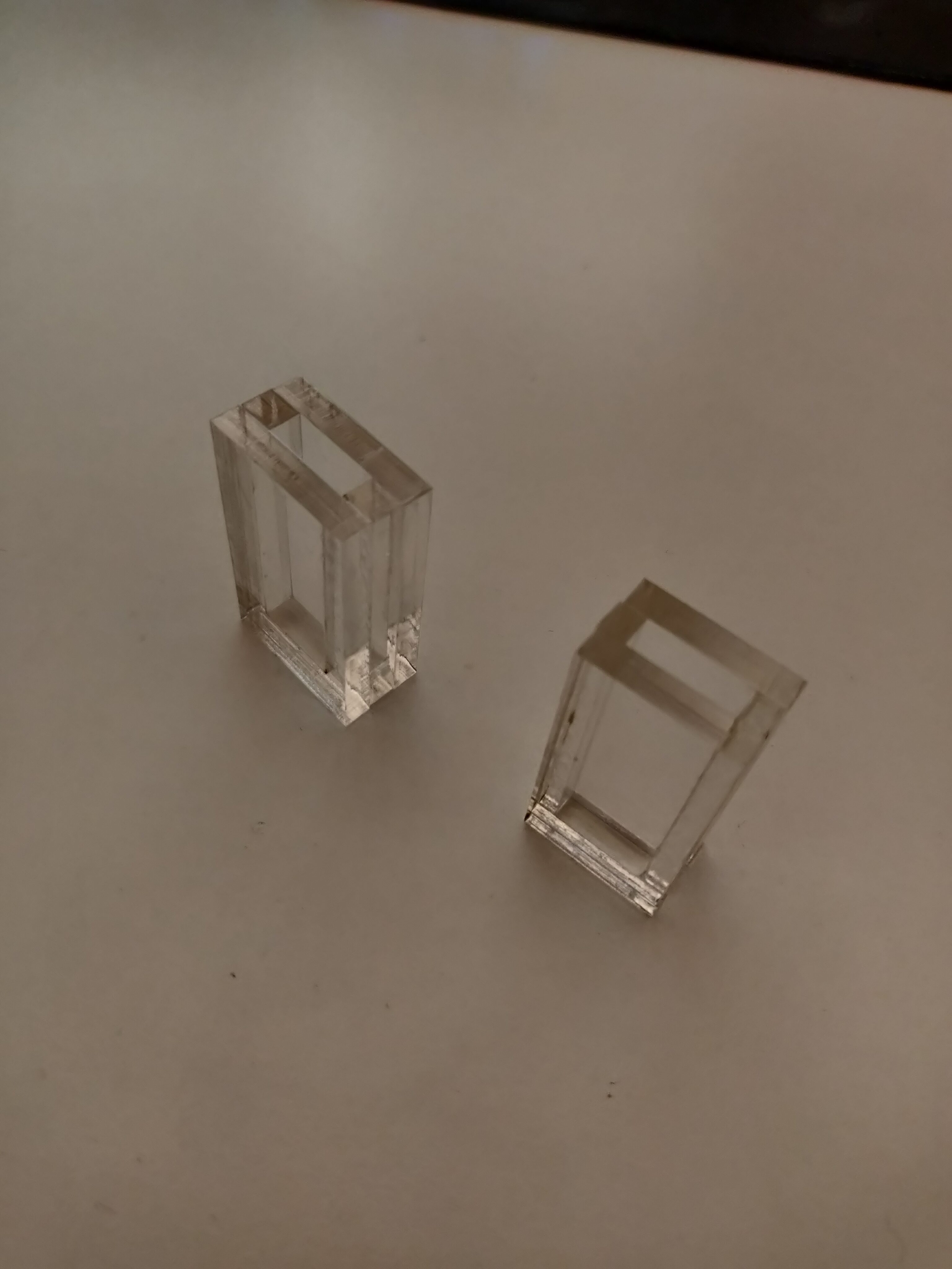
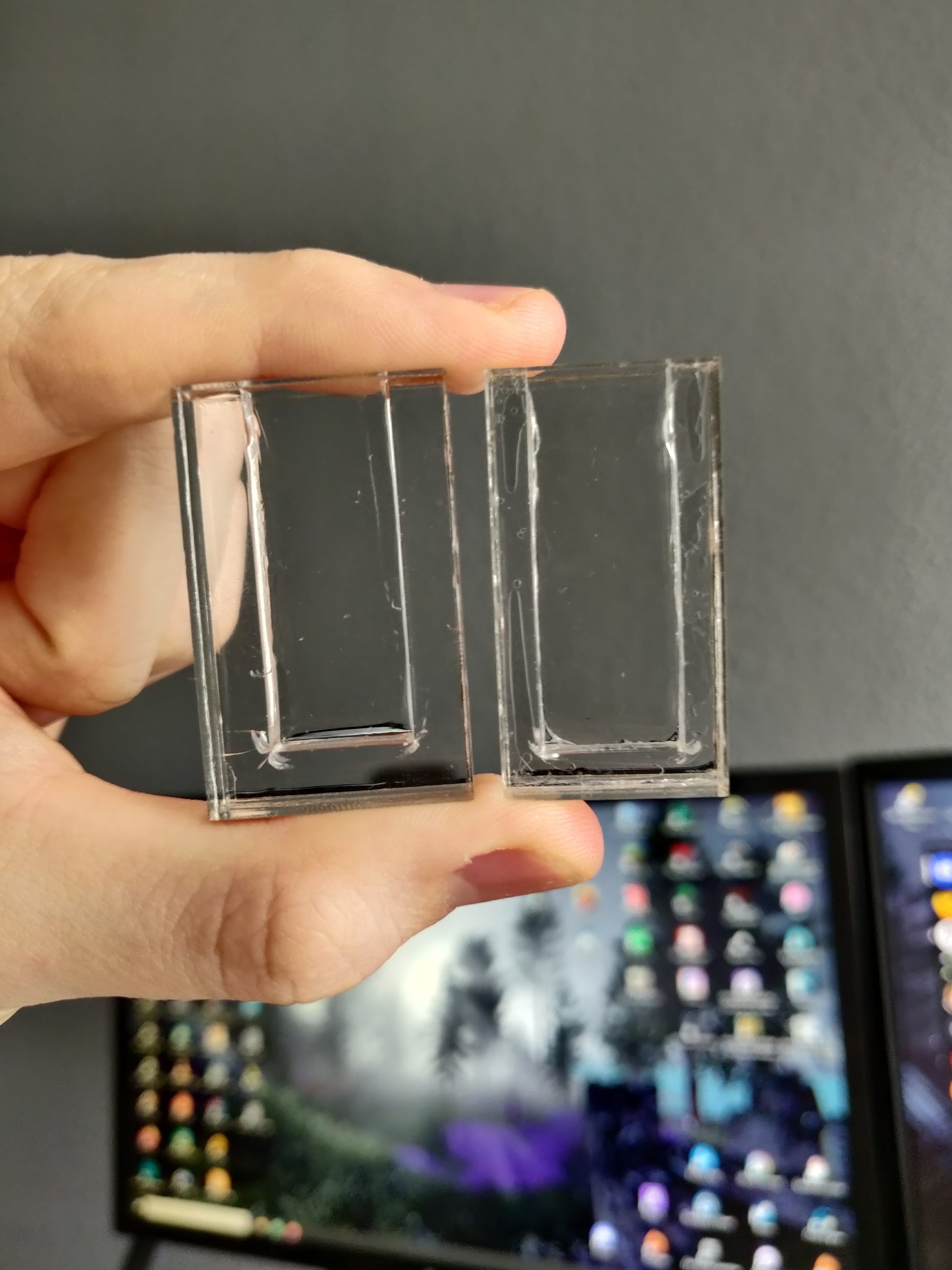
    Initial attempts to make some small test “cups” looked promising – the layers stuck together quite well, though sharp corners were prone to cracking.

    They seemed to be watertight as well, having no obvious leaks. To make sure, I filled them with ink, which revealed that one of my test pieces was not watertight on the inside edges – but it did still seem to hold on the outside.

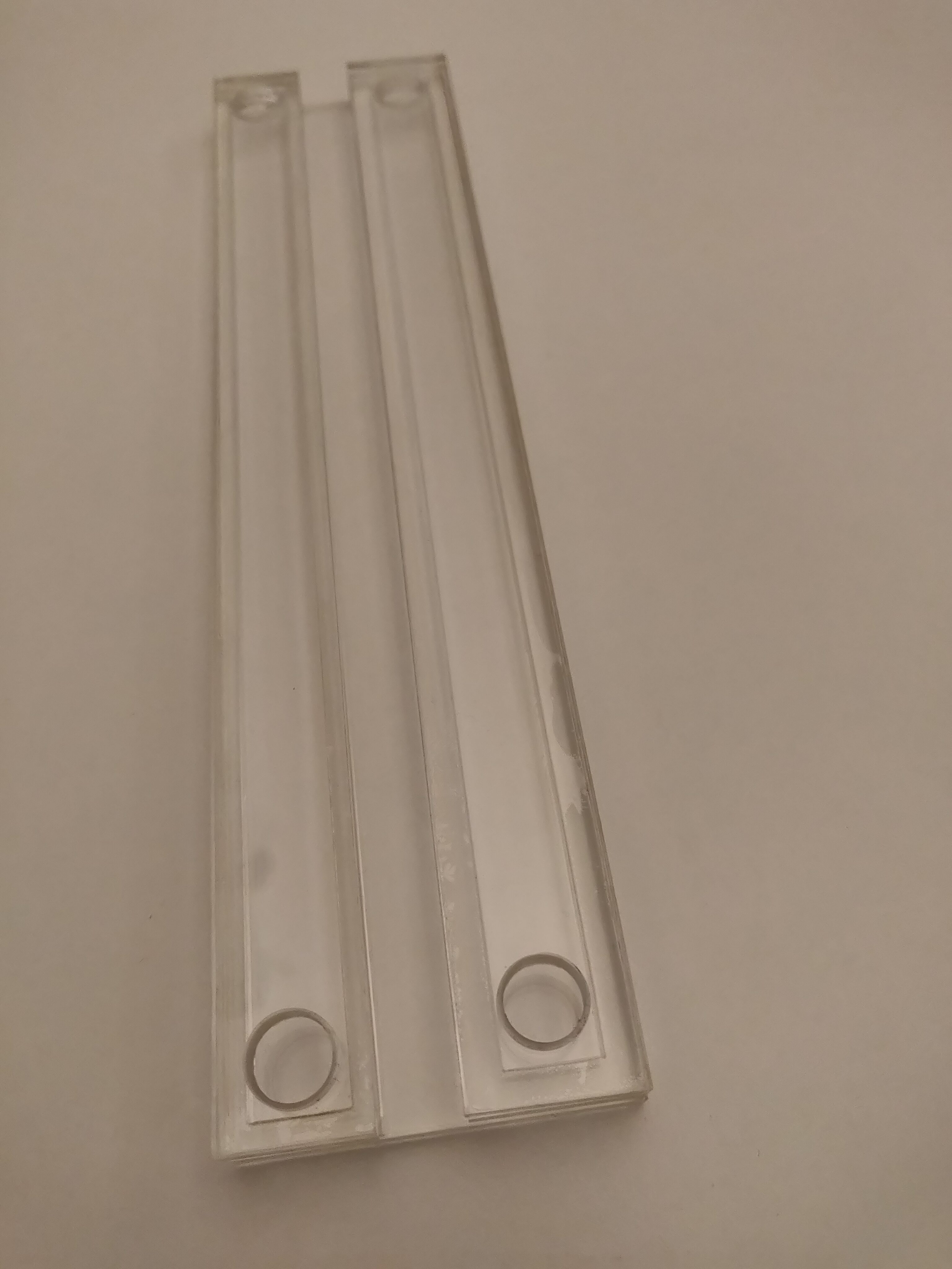
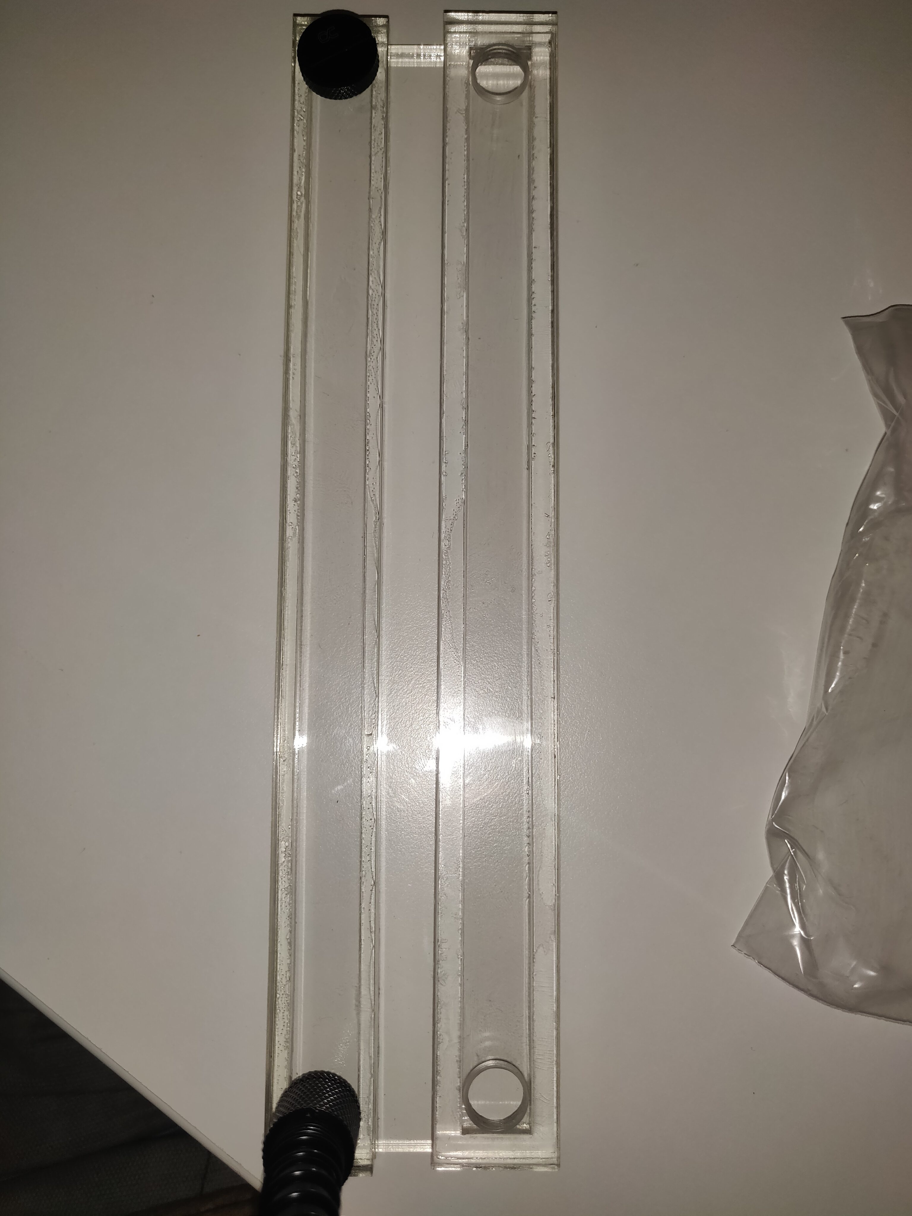
    While this “partial” seal didn’t instil much confidence, I decided to carry on with my other test: Making some actual test channels and checking them for airtightness.

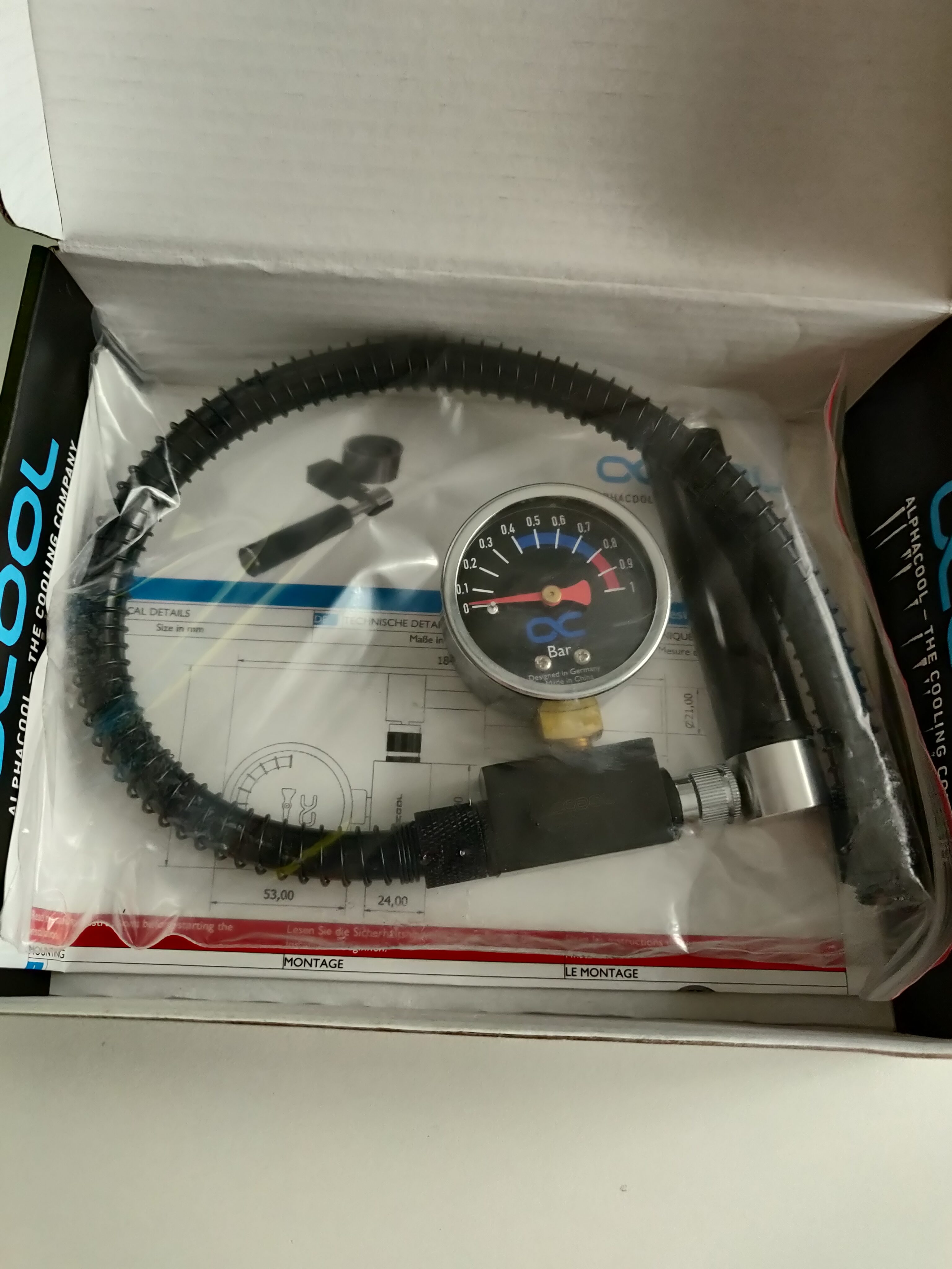
    I ordered a leak testing tool from Alphacool, designed for PC liquid cooling. Using it on the channels (with one end plugged) showed that they seemed to be perfectly airtight, which was good enough for me, so I decided to carry on with that idea.

    In hindsight, I should have been more suspicious of the “partial seal” I noticed earlier – but at this point, I was blissfully unaware of that.
    Therefore, satisfied with the test results, I started designing the case itself.