Multitool – The Schematic

The schematic for the Multitool is split into five pages:

  • Page 1: Controller & direct peripherals
  • Page 2: Power management
  • Page 3: Keyboard
  • Page 4: Volt-/Ohmmeter analog frontend
  • Page 5: Audio amplifier

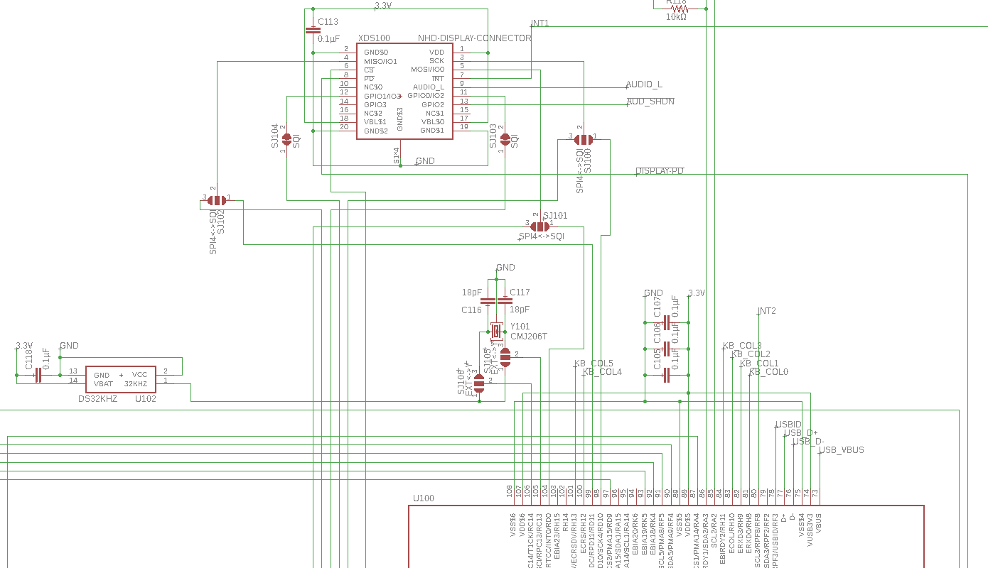
So let’s start with the first page, here it is in all its glory:

Schematic page 1

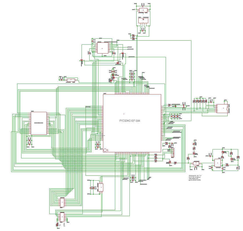
At the center you can see the brains of the whole device – the Microchip PIC32MZ2048EFH144 microcontroller. Most of its 144 pins are multifunctional to allow the chip to be configured for any design requirements. It boasts a rather high clock frequency of 200MHz and it has an integrated hardware floating point unit, which is why I chose this model for this project (hardware floating point means faster calculations with real numbers). To the left of the controller is the external 1MB RAM chip, and otherwise surrounding it are multiple peripherals and support components:

Display module connector, real time clock oscillators
Main CPU clock crystal, SD card slot
External I/O connectors, digital-to-analog-converter for analog outputs
Chip programming connector, manual reset circuit
Ambient light, temperature and humidity sensors (because why not)

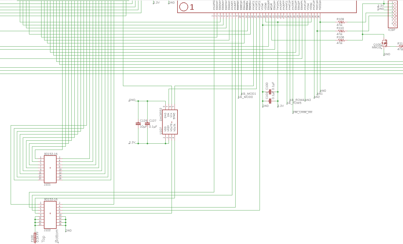
Most of these peripherals are simply direct connections between the I/O pins of the peripheral chips and the corresponding pins of the microcontroller (which I planned out beforehand). The manual reset circuit is an exception, it’s a little timer I designed (based on the well known 555 timer chip) which makes the reset signal trigger when the reset button has been pressed and held for a couple of seconds.

The second schematic page is all about power:

Schematic page 2

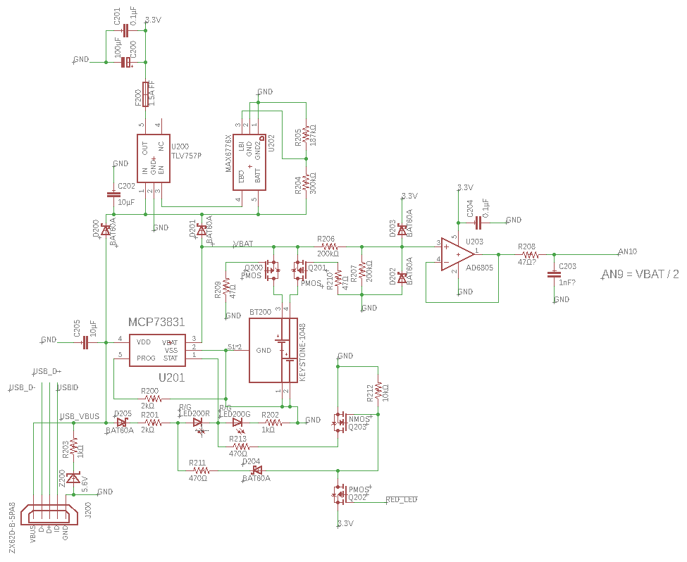
The best way to think of this page is that power travels from bottom to top. At the very bottom is the USB connector (the main power input), above that is the battery holder and the MCP73831 battery charge controller (powered from the USB connector). Around that are lots of support components and a red/green LED to show the charge status.
Just above the battery holder are two transistors for reverse polarity protection and an analog buffer that connects to the microcontroller to allow it to sense the battery voltage.
At the top left is the main voltage regulator, which is an LDO linear regulator that outputs 3.3V for the rest of the device through a fuse. Finally, next to that is a battery monitor chip that shuts off the system power if the battery voltage drops too low, to prevent damage to the batteries due to over-discharging.

Let’s see the third page:

Schematic page 3

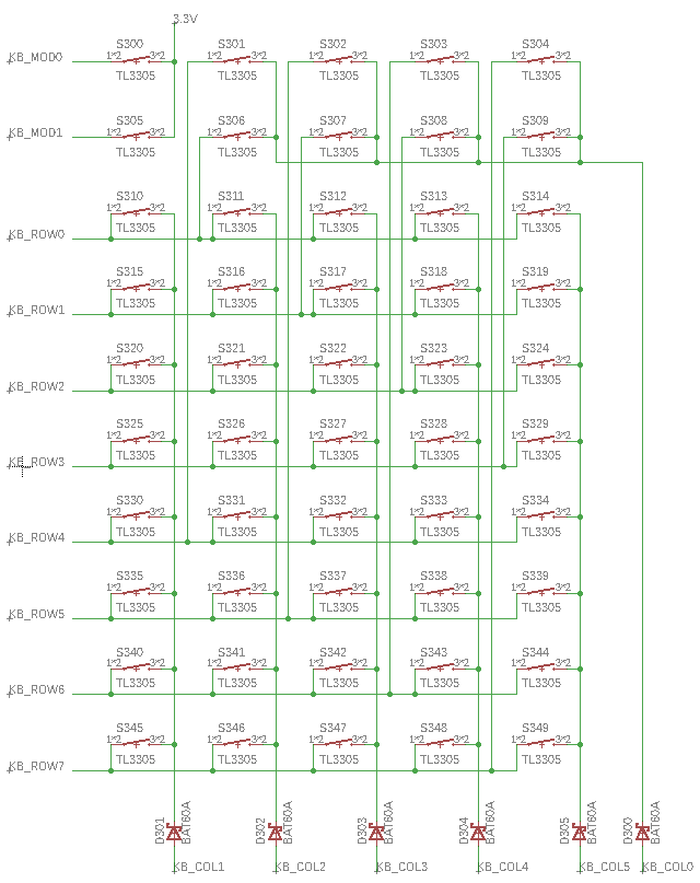
There’s not much to say about this one. The 50 keyboard buttons are arranged in a typical grid pattern, with common row/column connections. They are connected in 6 columns and 8 rows, which makes 48 buttons, and the remaining two buttons in the top left are connected individually, as they will act as modifier keys (like Shift/Ctrl/Alt on a computer). Due to that, column 0 is not physically connected as a column, but instead connects the top right 8 keys (in the same rows as the two modifier keys).

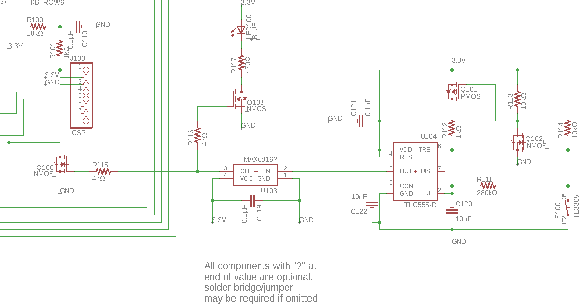
Page 4 has some analog electronics fun:

Schematic page 4

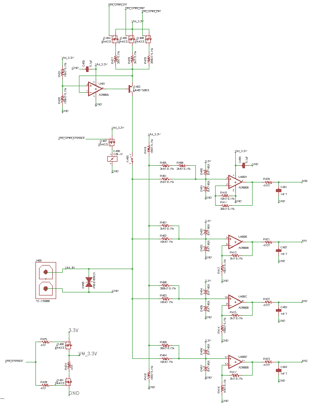
Let’s start with the bottom part:

Schematic page 4 – bottom

In the bottom left corner we have a global on/off switch for the module implemented with 2 transistors. The probe connector is right above it and is directly connected to a 600V ESD protection diode to protect the circuit from extreme voltages.
To the right you can see four similar analog frontend circuits, acting as four voltmeter sensing ranges (the top one is cut off in the second picture).
The input voltage first goes through a precision resistor voltage divider that is connected to a 1.65V voltage reference (implemented using another resistive divider). This is done to shift the center point of the voltage range from 0V to 1.65V, which is half of the supply voltage of 3.3V. This results in the specific voltage range, e.g. ±5V, being shifted to within the system voltage range of 0-3.3V. That voltage range is then ensured by clamping it between the positive and negative rails using diodes, after which it’s buffered, amplified, filtered and connected to analog inputs of the microcontroller.
The ranges of the circuits are, from top to bottom, ±0.5V, ±5V, ±50V and ±500V.

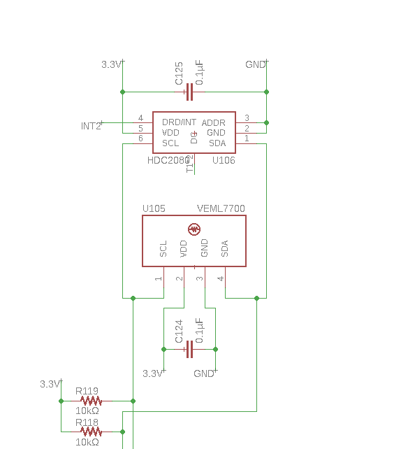
Now for the top part of page 4:

Schematic page 4 – top

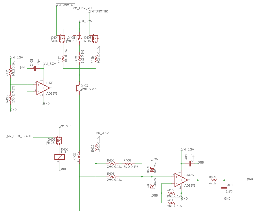
At the bottom is the ±0.5V range explained above.
Next to it you can see a relay that connects the measurement voltage rail to the current source above. It’s designed to drive one of three selectable constant currents through the measurement probes (1µA, 100µA or 10mA). If it succeeds, the voltage across the probe terminals (measured with the voltmeter module as usual) is equal to the (known) current multiplied by the resistance between the probes. So by enabling and connecting the current source, the voltmeter acts like an ohmmeter instead, and can theoretically measure resistances up to 3MΩ.

Now the final page:

Schematic page 5

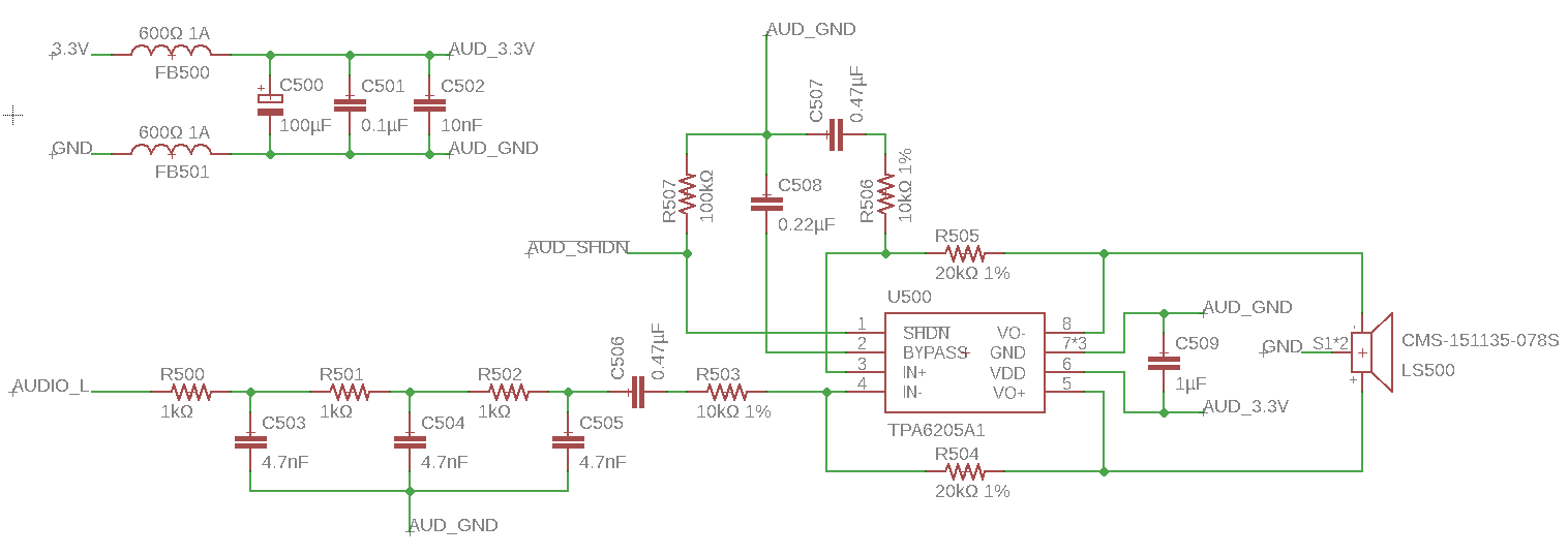
This part of the schematic is mostly copied from the display module datasheet. It’s nothing more than a basic low-power mono audio amplifier with tons of filtering on the input and power supply rails.

And with that, we’ve covered the entire schematic of the Multitool! Looking back at it, there are some things I’d do differently today, but this was the first large schematic I designed myself and I think it’s quite good for that.
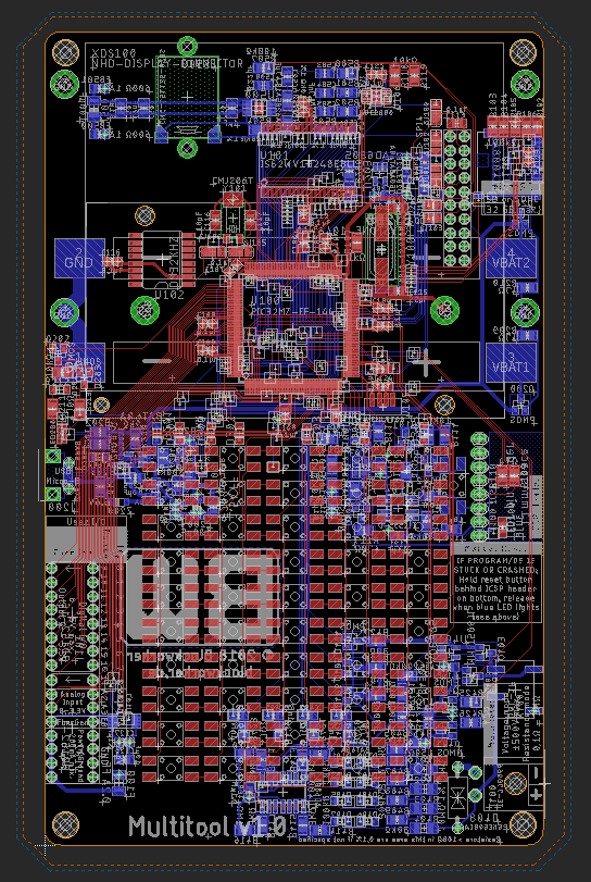
Next we’ll be looking at the circuit board that I made out of this.
Link: Coming soon 🙂

See you around,
BlockWorker

Multitool – The Design

It’s been quite a while, but it’s time to share the circuit design with you all. But first, here are some changes I made to the specs listed in the initial post:

  • Switched the screen from the -CSXN-CTP model to the -CSXN-T version: (worse) resistive touch instead of capacitive, but significantly cheaper
  • Voltmeter now capable of -500V to +500V input (instead of 0-300V), which also makes it suitable for AC!
  • Added Ohmmeter functionality for measuring resistance
  • Added user-friendly reset circuit (in case the controller crashes)
  • Added brightness, temperature and humidity sensors (because I can)
  • Extended unused controller pins to a header for external connections:
    • 18 digital I/O pins
    • 4 analog inputs
    • 2 analog outputs (using an additional DAC chip)

With that out of the way, let’s get to the point.
One of the first things I chose is the board size: 150 x 92 mm. The width is based on the size of the screen assembly, and the height is chosen to feel nice when handling it (and also to fit the keyboard without putting the buttons too close together).
Then, with my planned features in mind (and coming up with new ones all the time), I downloaded Autodesk EAGLE (student edition) and started creating a schematic and figuring out the exact specifications and functional requirements of the system. After that was done, I started laying out and routing the PCB. After a few months of work, I ended up with this 4-layer work of art mess:

The PCB, looking “through” it from the top.

I will go over the entire schematic and PCB design in detail, but it won’t fit in a single post. Therefore I will split it into multiple posts and link them here:

Also, if you want to look at the EAGLE design files yourself, here they are:

Be aware that you (probably) can’t open these files in the free version of EAGLE. I’d love to offer a “free-compatible” version of the design, but unfortunately it exceeds all three limitations of the free version: schematic sheet count, PCB layer count and maximum PCB area.
However, if you are a student (like me), you can get the student version of EAGLE for free, which is functionally equivalent to the premium version.

See you around,
BlockWorker

The Multitool Project

UPDATE: Design overview here!

After 12 (long) years, I recently finished school. That also meant giving back all of the things that were provided by the school. Most of them were just books, but there’s one thing in particular that I will miss:

The TI-83 Plus graphing calculator. It’s a very useful (and powerful!) tool that helped me a lot in school, but was also quite handy at home and for my past projects. It has a lot of features outside of basic math, like equation solving, integration and differentiation, statistical analysis, matrix operations, programming support (in its own language, TI-Basic) and of course a lot of options for graphical presentation and analysis of functions and graphs. You can even put games on it, if you have a USB-to-calculator link cable. Yes, that was a lot of fun, especially in 8th-9th grade.

But the TI-83+ is definitely not perfect. It’s a very old design based around the Zilog Z80 processor (which was designed in 1976!), its display is monochrome and has a low resolution of 96×64 pixels and most importantly, the device is massively overpriced for its age at around 80$. To put that in context: Nowadays you can get a low-end smartphone for that much money, download some free apps and you have something way more powerful than the 19-year-old calculator with a 42-year-old processor.

But even then, I feel that there is something about having a dedicated calculator with physical buttons that cannot quite be replicated by a smartphone app. And I really miss being able to just reach across my desk and have any basic calculation done in a few button presses without having to unlock my phone, look for the right app and then type something in using a touchscreen keyboard. So I thought: I’m a computer scientist and engineer at heart, so why not build my own calculator? And if I go that far, why not add all kinds of other useful features to it?

That’s how the Multitool project was created.
The idea is to design and build a modern calculator-sized tool that can help me in all kinds of ways in future projects and in everyday life. I am currently still in the middle of planning and designing it, but here are some specs as of now:

  • Processor: Microchip PIC32MZ2048EFH144 (32-bit microcontroller, 200 MHz, 120 I/O-pins, 512 kB RAM)
  • 1 MB of external RAM (yes this seems tiny, but is probably more than I need)
  • Display: NHD-3.5-320240FT-CSXN-CTP (3.5″ diagonal, 320×240 resolution, full RGB, capacitive touchscreen, integrated graphics chip)
  • 50 button keyboard
  • USB micro-B connector (a.k.a. non-Apple-smartphone USB connector)
  • MicroSD card slot (supports cards up to SDHC, so max. 32 GB)
  • Battery: two 18650 Li-Ion cells, USB-charged at 500mA (yes that’s slow)
  • Audio: 0.7W mono speaker
  • DC voltmeter circuit up to 300V

Other than that, I still have a few ideas for modules and additions, but I haven’t looked into how easy those are to implement (and whether I really need them heh). If you have a suggestion for what to add, please comment below 🙂

I’m really excited to finally share my projects with the world, so I will post any updates to the project here and when the design is (almost) done, I will go over the implementation details and schematics here, essentially documenting and explaining the device and my design process.
(for updates see top of post)

See you around,
BlockWorker