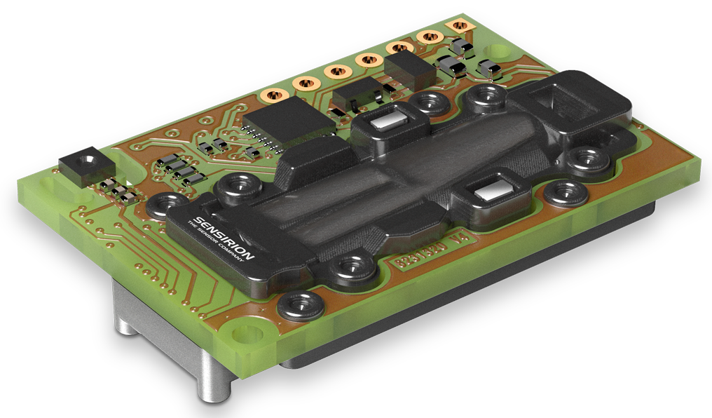
The first design requirement I chose, using a true CO2 sensor, seemed like a good place to start. After a quick search, I found the Sensirion SCD30 module, which seemed like a perfect centrepiece for the CO2 Station design.
It’s based on a high-performance infrared CO2 sensor and includes temperature and relative humidity sensors, all in a single device, with an easy-to-use serial interface (I2C).

The next big question was the choice of display. I really wanted a high-quality display that could show the measurement values in a large font, looking as visually appealing as possible.
The typical choice for that would be a backlit LCD screen – but here, its high power consumption would make the “long battery runtime” requirement impossible. Reflective segmented LCD displays, like in digital watches, are perfect for low-power use cases, but they’re not very accessible for single-piece projects like mine.
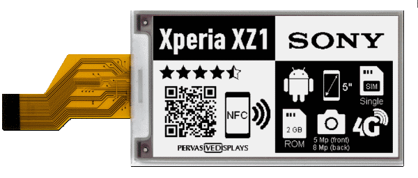
Therefore, I decided to try out a new technology – an “E-ink” or “E-Paper” Display (EPD), as commonly seen in E-Book readers.
My search led me to a Pervasive Displays 3.7″ display panel1, which I decided to use for this project, with its form factor and size being great for what I wanted here. Also, it offered an integrated display controller, which was very helpful – worrying about the intricacies of driving an EPD manually would not have been fun.

The EPD needed a corresponding connector for its FFC (flat flexible cable), as well as some support components – essentially an entire external boost converter, controlled by the EPD.

With that, I had the central components of the design. Next, I chose a low-power central system controller (PIC24F GU series), which would communicate with the sensor and EPD, allow user interaction through buttons and a signal LED, time periodic updates using its integrated real-time clock, and offer a USB interface for configuration.

For powering the device, I decided on a single Li-Ion 18650 cell in a holder. It could be charged from USB using a battery charging controller (DIO5508), and would power the system through a voltage converter (boost-passthrough converter followed by a linear voltage regulator), to ensure the system voltage would always be at 3.3V, regardless of the battery’s state-of-charge. For this design, the Texas Instruments WEBENCH Power Designer was very useful, as in past projects.
For additional protection of the battery against deep discharging, I also added a MAX6775 battery monitor, to shut down the system if the battery voltage drops too low.

Designing the PCB was a little different this time, compared to my previous projects – I decided that the best way to mount the display would be on the PCB itself, so the majority of the front side area was reserved for that. All other components, aside from the user buttons and signal LED, had to go on the back side. Additionally, I needed some way to mount the PCB assembly in a enclosure later, so I added some right-angle screw terminals in the corners.

Now, the only missing part of the design was the enclosure. Using Fusion 360, I quickly designed a small wooden box for it (out of 5mm plywood).
I could have designed it to be built by hand, it wouldn’t have been too much work – but after the BlockBox v2’s success with CNC machining, I decided I might as well do more of that – it’s fun and produces really good-looking results.


With everything designed and planned out, it was time to order the parts, and build this thing!
- The exact EPD model I used is no longer available at the time of writing, but equivalent and improved successors exist. ↩︎