
Find the introduction here. Previous parts: 1, 2, 3, 4.
Program Counter
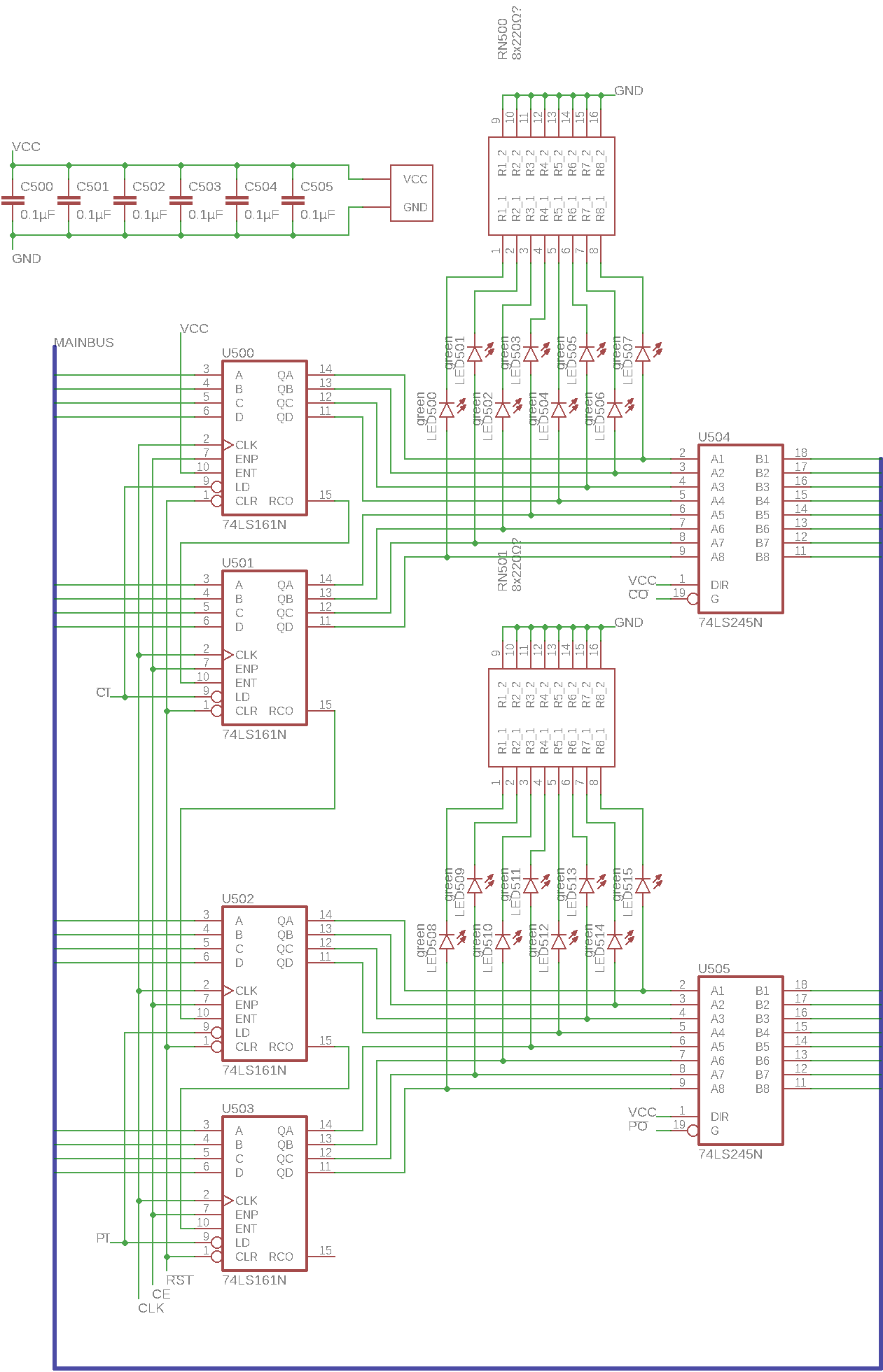
Another one of Ben’s modules that’s been slightly expanded, the program counter is a basic tool that is required for program execution: The computer needs to keep track of its current position in the running program. That way it always knows where in memory the next instruction can be found. The program can also overwrite this counter with an arbitrary value, which has the effect of jumping to that point in the program.
The counter itself is implemented using four 74LS161 4-bit binary counter chips which are cascaded to create one 16-bit counter. As the data bus is only 8 bits wide, the counter input and output is divided into two virtual registers, P (higher 8 bits) and C (lower 8 bits). As usual, the output is managed using 74LS245 bus transceivers and there are some LED packs to display the counter value.
Instruction control logic
Now this module is where the magic happens: It tells all the other modules that we’ve seen what to do and when to do it. Ben’s version can be found here.
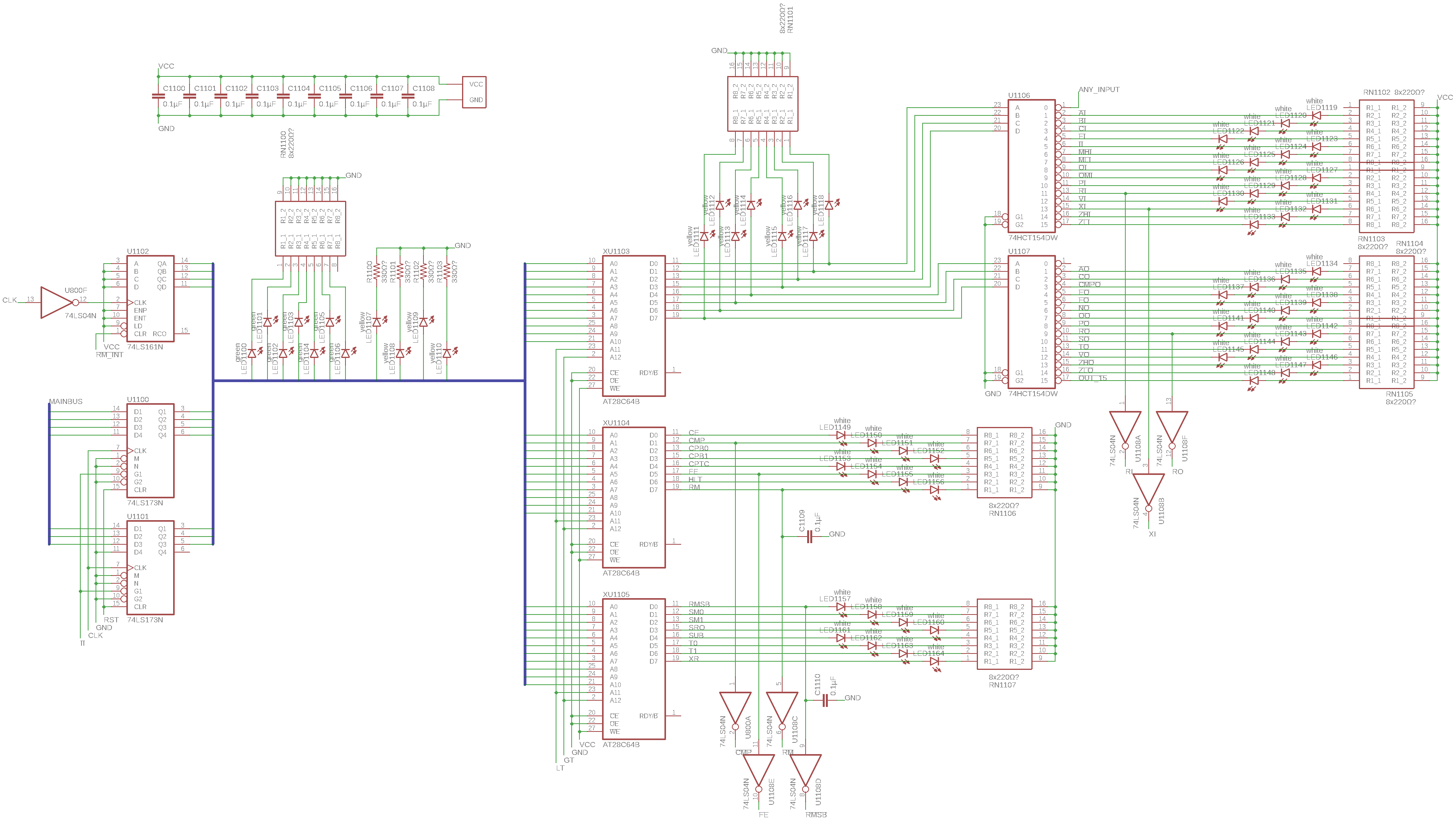
Let’s start on the left side: There are two 4-bit register chips that store the current instruction code, which is 7 bits long. Above that there’s a 4-bit counter that keeps track of the so-called microinstruction. Microinstructions are small steps that are exactly one clock cycle long and do a very basic task like moving a byte from one register to another. Multiple microinstructions are combined in sequence to execute an instruction which does something more complicated, like fetching a value from memory or adding two numbers. Afterwards a few extra microinstructions are executed to retrieve the next instruction from memory, this is called the “instruction fetch” cycle.
There are some LED packs to display the instruction and microinstruction values, and then these two values are fed into the next part of the circuit, which is combinational logic. Here it’s implemented using three ROM chips, similarly to the numerical output module (see part 4). This logic translates the instruction code and microinstruction step into the control signals that are fed to all other modules in the computer (input enables, output enables, other behaviour controls). The topmost chip’s outputs are fed into two 74HCT154 1-of-16 selectors (also called demultiplexers). This way the 8 bits from the ROM output can be expanded out into 16 input enable controls and 16 output enable controls, using the fact that only one input and one output need to be enabled at any point. All these control signals are displayed using some white LEDs and some of them are inverted if the corresponding modules require a different signal polarity.
To help the computer’s timing, the microinstruction counter increments on an inverted clock pulse (see the inverter left of the counter chip). This way the computer alternates between executing a microinstruction (rising clock edge) and setting the control signals for the next microinstruction (falling clock edge).
The details and implementation of instructions will be discussed in a separate post, for now, let’s look at the PCB that I made from this schematic.