
Find the introduction here.
In the previous post I explained the schematics of the different modules of the computer. Based on those, I made a PCB (printed circuit board). You can click the images to zoom in.
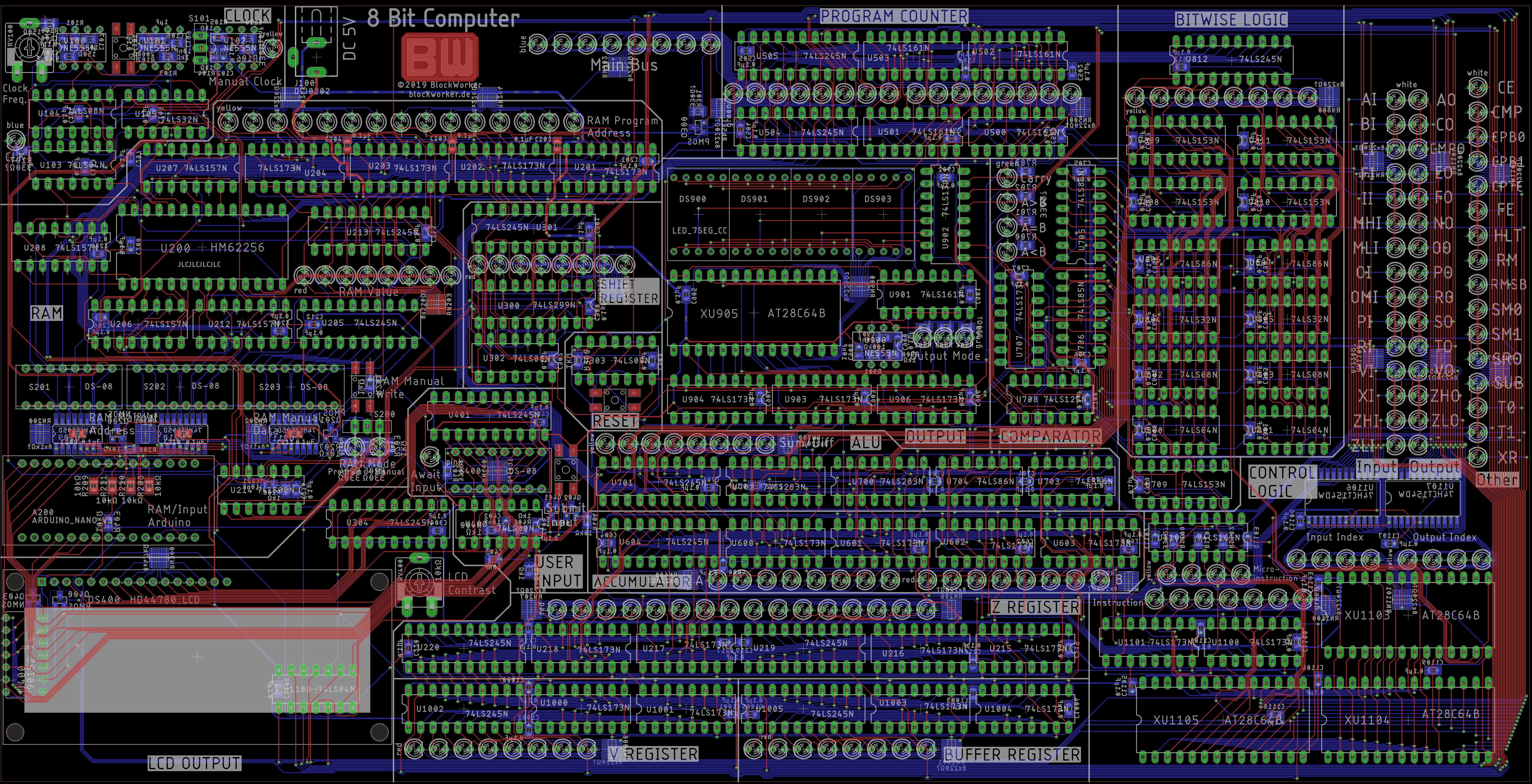
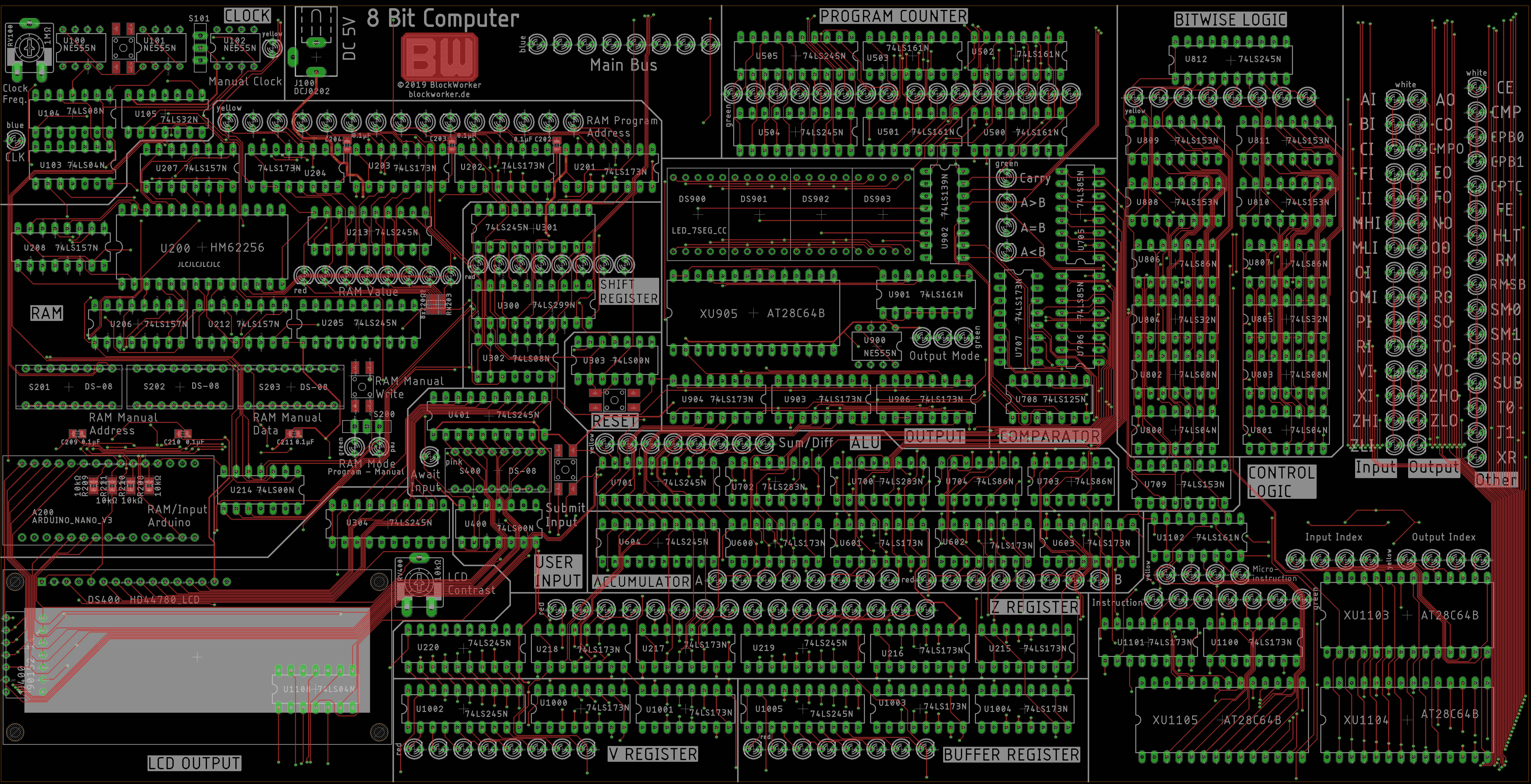
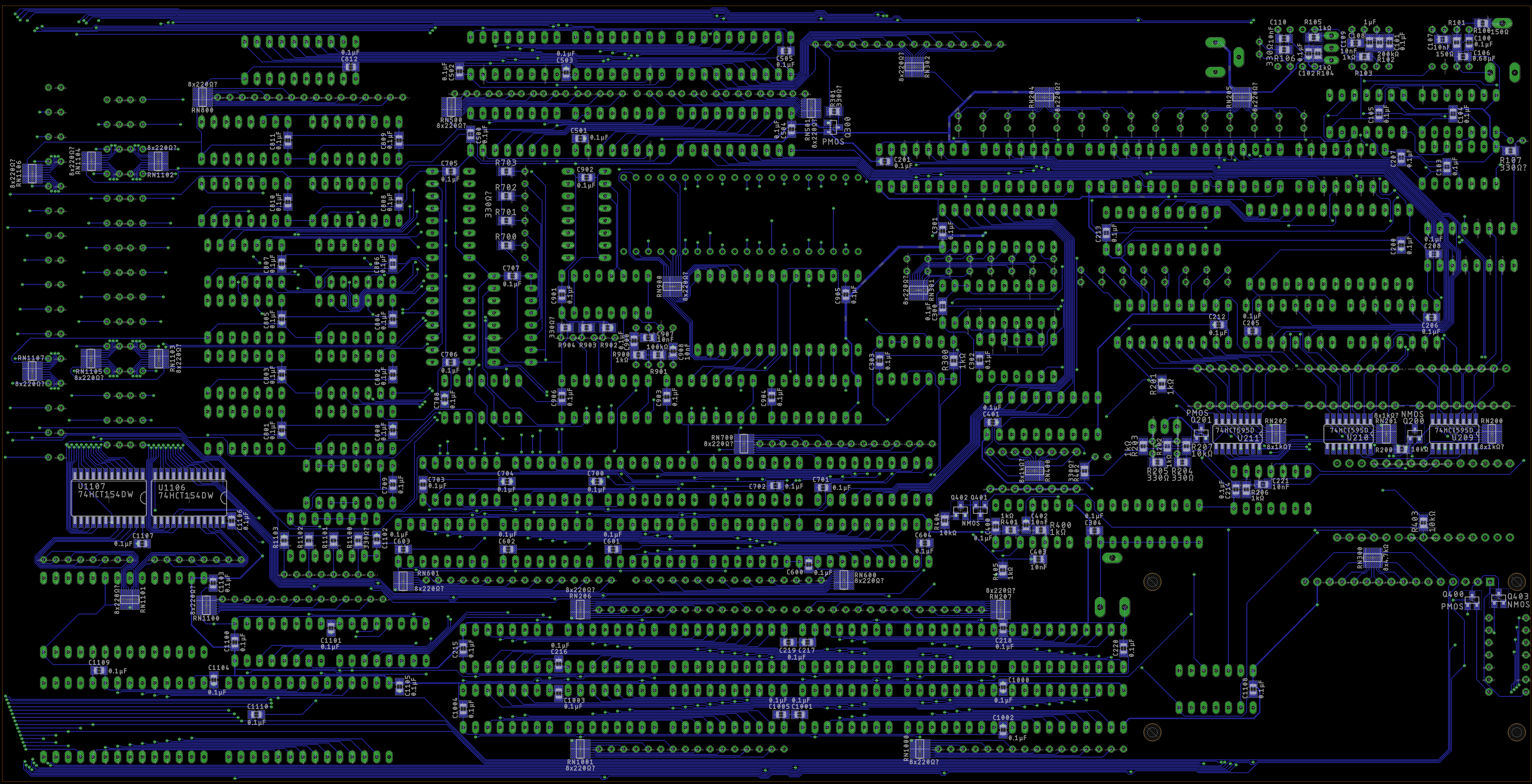
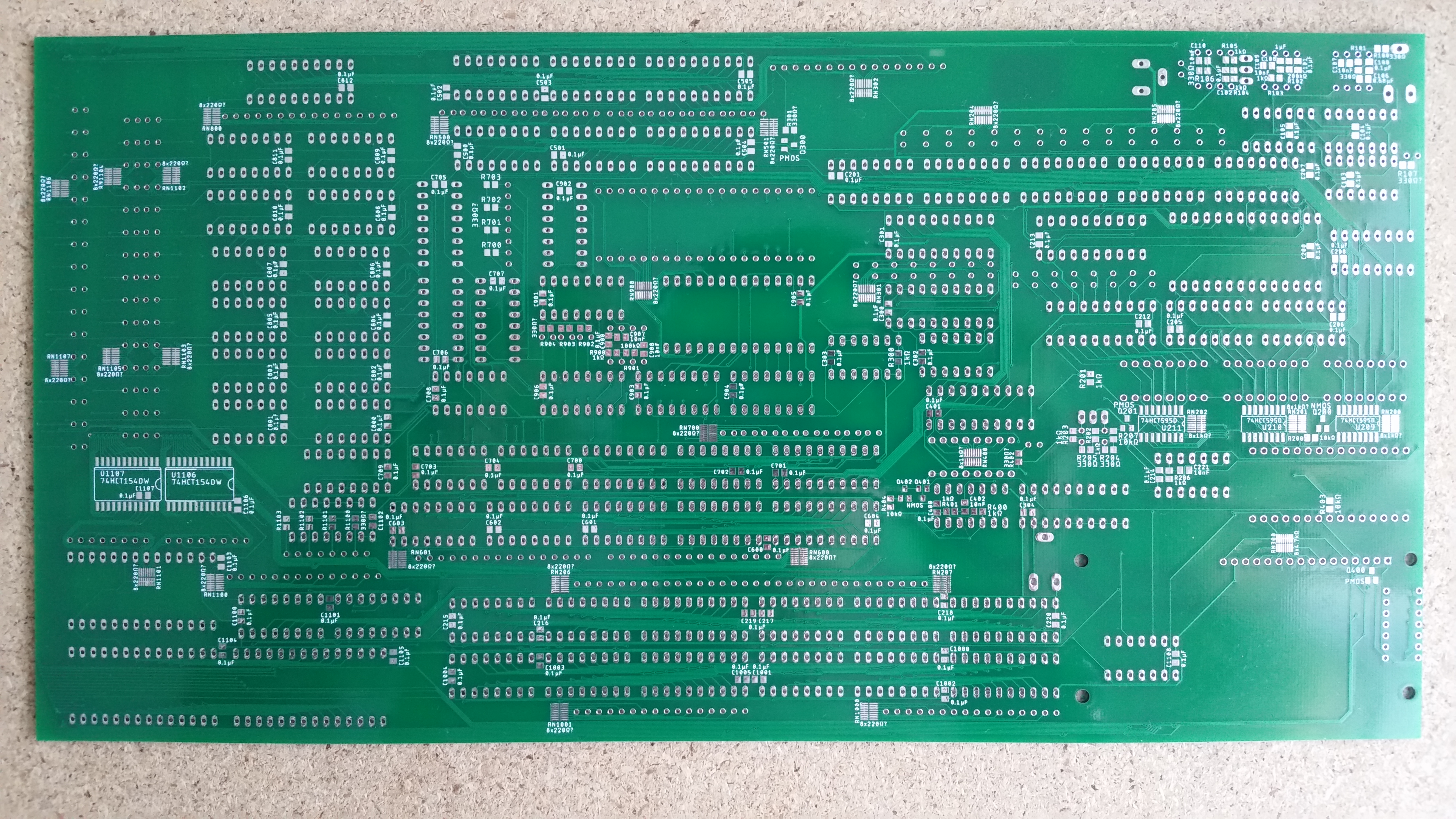
As you can see, the board is quite cramped. I wanted to reduce the board size as much as possible to save costs and make it more portable. This made signal routing quite challenging, as the through-hole component pads (green) don’t leave a lot of room for the over 2000 wire connections required. I also fit it all into 2 layers (top and bottom), I didn’t want to use a 4-layer PCB as it’s significantly more expensive and I believed that it could be done with just 2. It seems that I was right.
The total board size is 31.5 x 16.1 cm (12.4 x 6.4 inches), which is a lot smaller than I initially expected, considering the breadboard prototype was about 40 x 40 cm (15.7 x 15.7 inches).
I wanted to keep the individual modules visually separated on the board to show how the computer is made of these somewhat independent pieces working together. I went through multiple layout iterations for each module to make it stand out as a separate entity but still fit in well with the other modules. Additionally I added some thick lines on the silkscreen as rough outlines between the modules and labeled them all. The LEDs are also arranged in nice bit strings in the correct reading order and labeled if necessary.
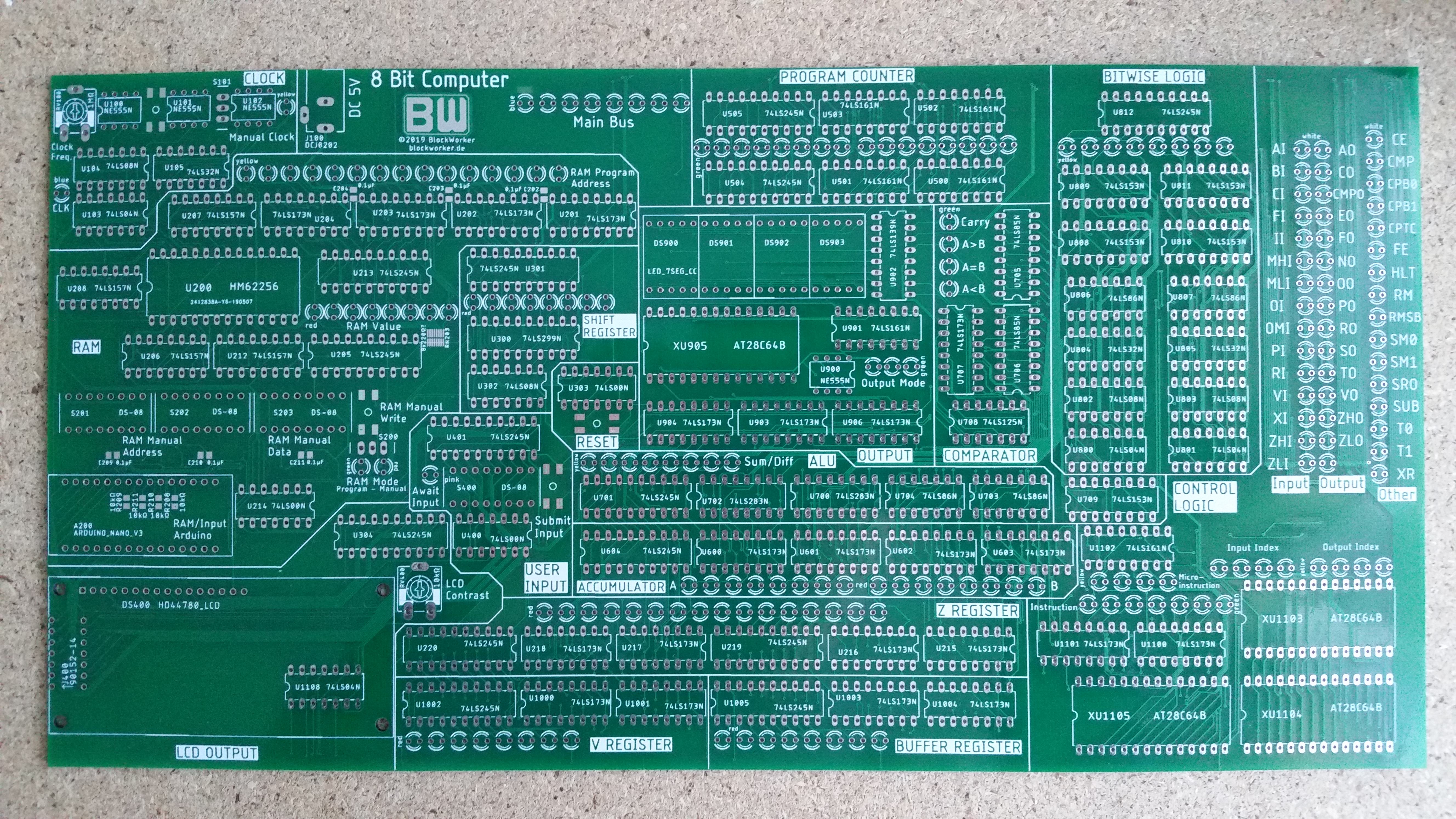
Here’s the raw PCB, fresh from the friendly neighborhood chinese factory:
And here are some impressions from the assembly process:
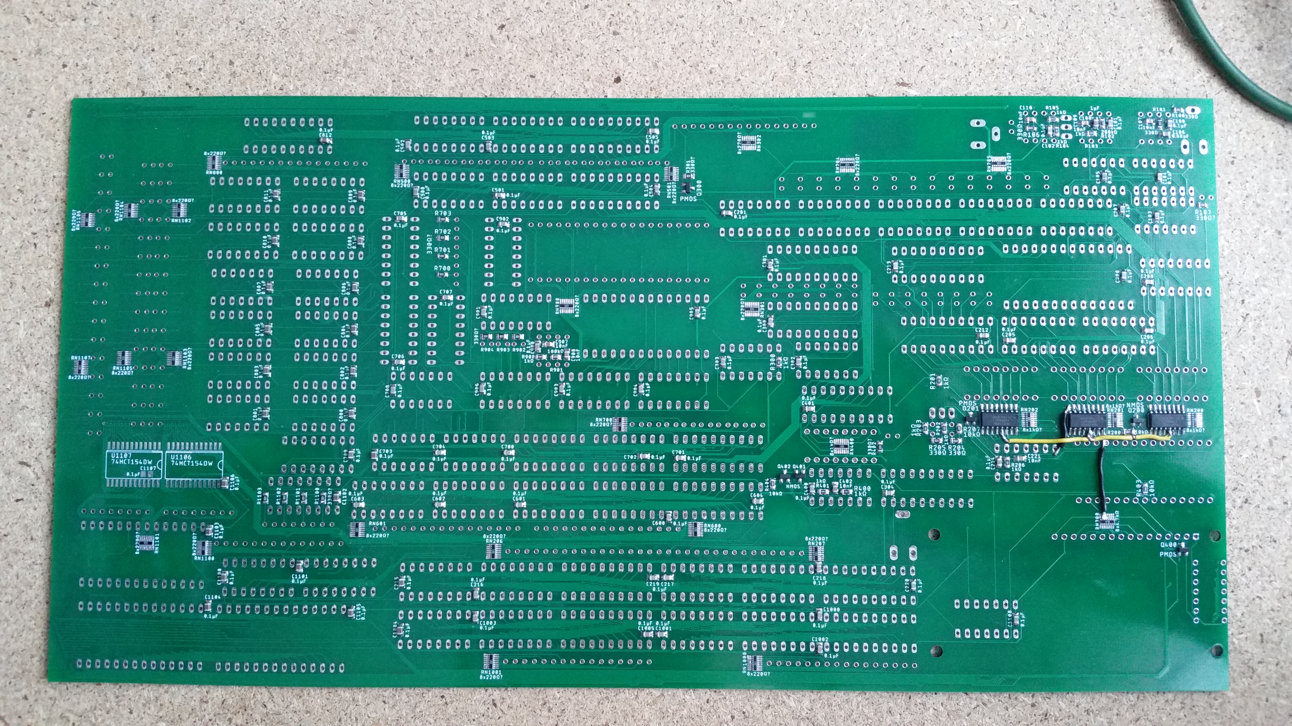
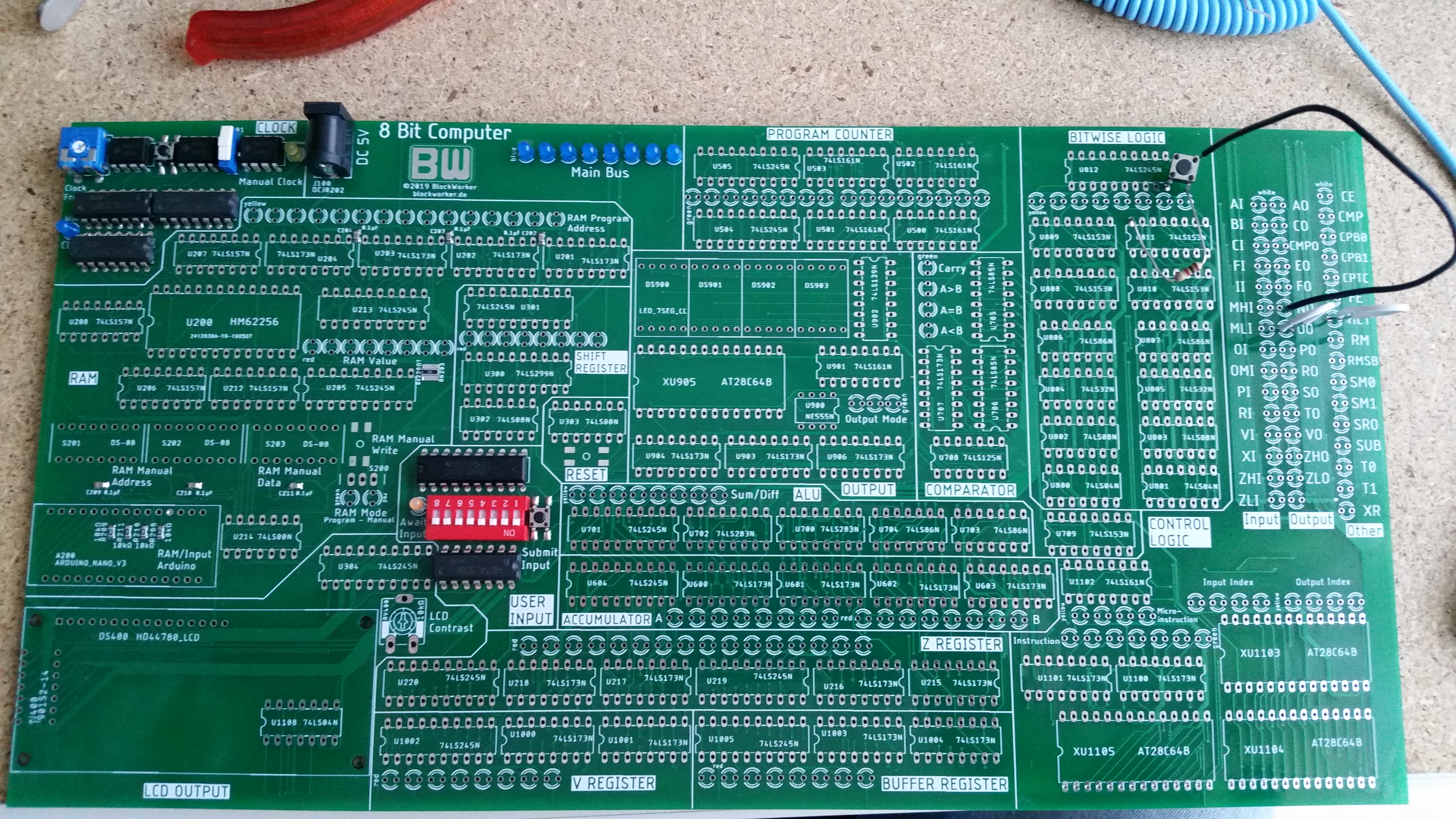
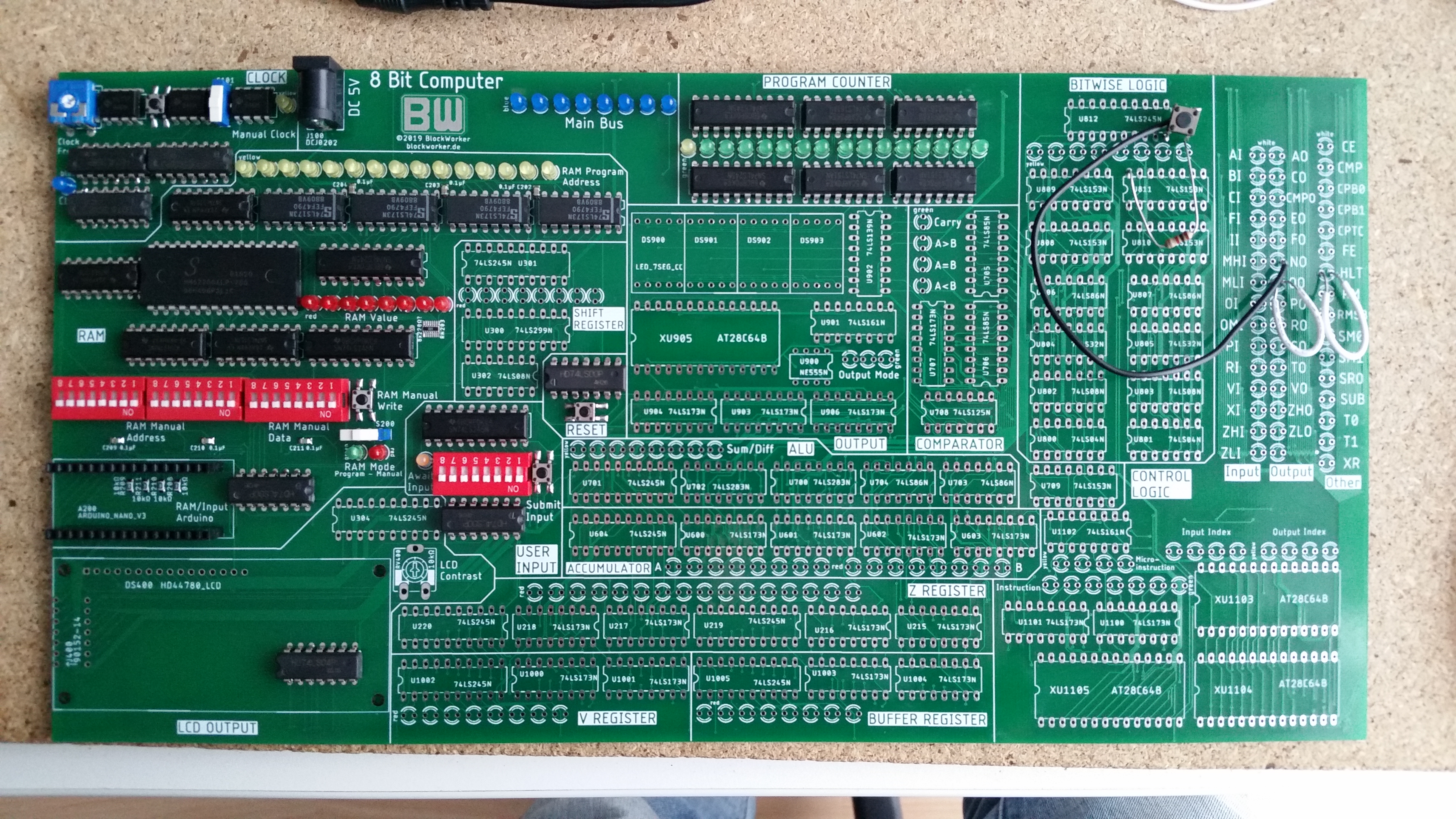
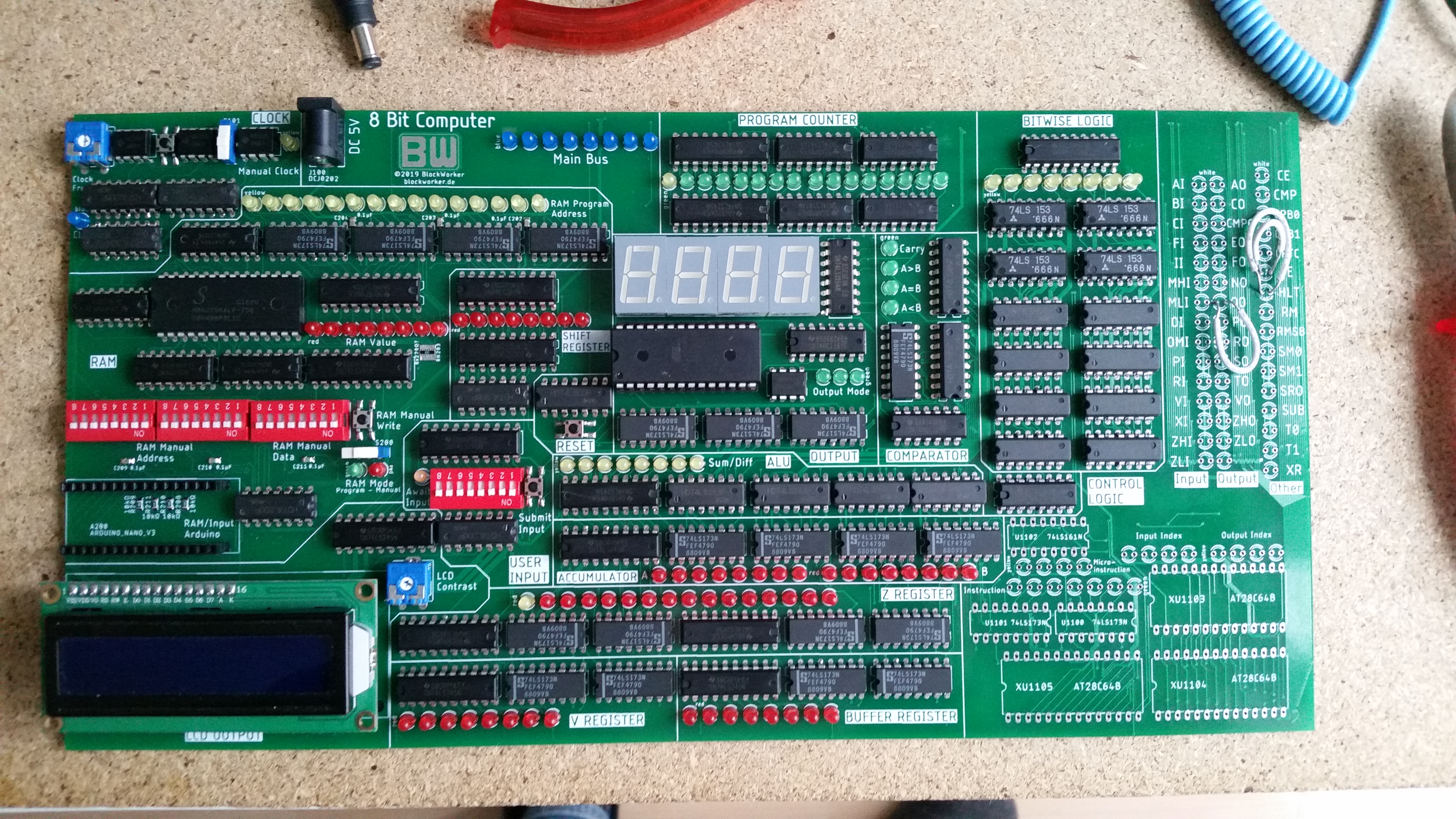


The assembly was surprisingly fast, it only took about a week. Most of it was rather repetitive, soldering thousands of component pins, but seeing it come together felt great anyway.
Now that the PCB was assembled, there was still one thing missing for the computer to work: Programming the instruction behaviour. This is what we will look at next.