
Find the introduction here. Previous parts: 1, 2.
The Arithmetic Unit and Comparator
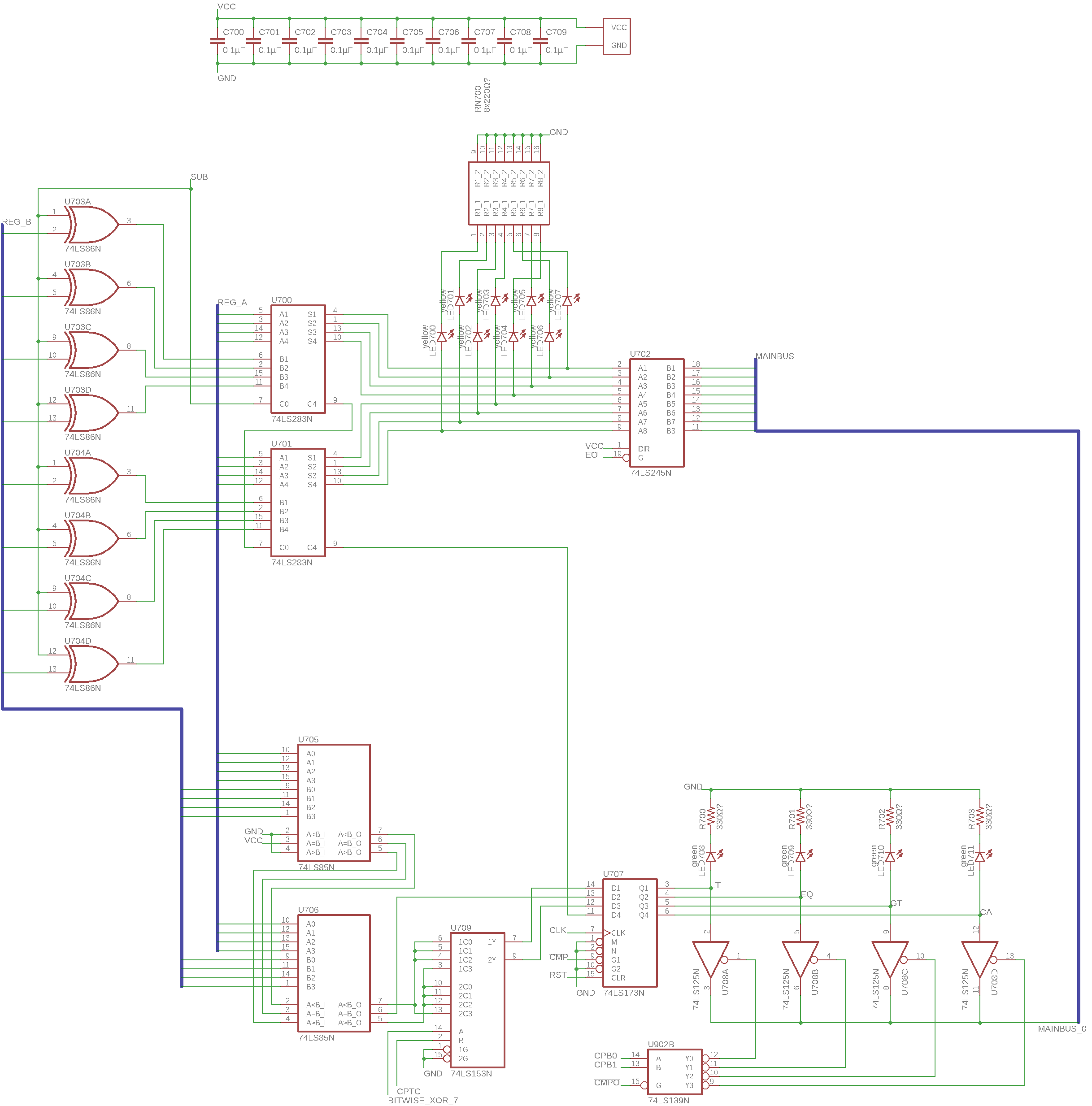
Here we have two very useful modules. The first one is the arithmetic unit, which can do addition and subtraction (top half of the page). Its main components are two 74LS283 4-bit adder chips (U700, U701) that are chained together to create an 8 bit adder. After the adder chips, there’s an LED pack to display the sum and a bus transceiver to output the value to the rest of the computer.
For subtraction, the module forms the two’s complement of B, effectively negating it, and then adds that to A. The two’s complement is formed by inverting every bit of B using the XOR gates on the left and then adding 1 (done here using the carry input signal of the first adder chip). If you have no idea what any of that means, you should probably check out Ben’s videos on two’s complement and this module – the module is identical to his design.
Something I never even thought of before watching Ben’s series is that an “add” instruction using this module doesn’t actually tell the computer to do the addition – the addition is always done and the sum is always available and can be seen on the LEDs. The only thing that an “add” instruction does is tell the computer to output that sum value onto the bus and store it in a register. Now that seems quite obvious and normal to me, but it blew my mind back then. There are a few more things I learned about computers during this project that made me feel that way – which is why I consider this a very successful and valuable project.
On the lower half of this page you can see the comparator module. It allows the computer to compare two numbers by magnitude, which is quite important as it opens the way to conditional branching – an essential concept in programming. It is implemented using two 74LS85 4-bit comparators (U705, U706) chained together, creating an 8-bit comparator. Next to that is a 74LS153 dual 4-to-1 selector (U709), which provides the selection logic that allows both signed and unsigned numbers to be correctly compared. Then there is a 4-bit register to store the states of the less than, equal, greater than and carry flags from both modules on this page, as well as some output logic that allows individual flag values to be output onto the main bus.
Magnitude comparison of unsigned numbers is done quite simply: The comparator first checks the highest bit of the inputs and checks if they’re different. If they are, the input value that has a 1 in that place is definitely larger than the other input value – and so the corresponding output (A<B or A>B) is turned on. If the highest bits are the same, it checks the second highest bits the same way, then the third highest and so on, until it finds a bit difference between the two inputs. If no difference is found after all bits have been checked, the numbers are equal, which is signalled using the A=B output.
For signed numbers in two’s complement format it seems a bit more complicated at first glance – but it turns out that the comparison can be done using the same 8 bit unsigned comparator, you just have to swap the A<B and A>B outputs if one input is negative and the other one isn’t. That is what the selector chip U709 does if a signed comparison is requested. If don’t see why that trick works, try it yourself (on paper)!
The Bitwise Logic Module
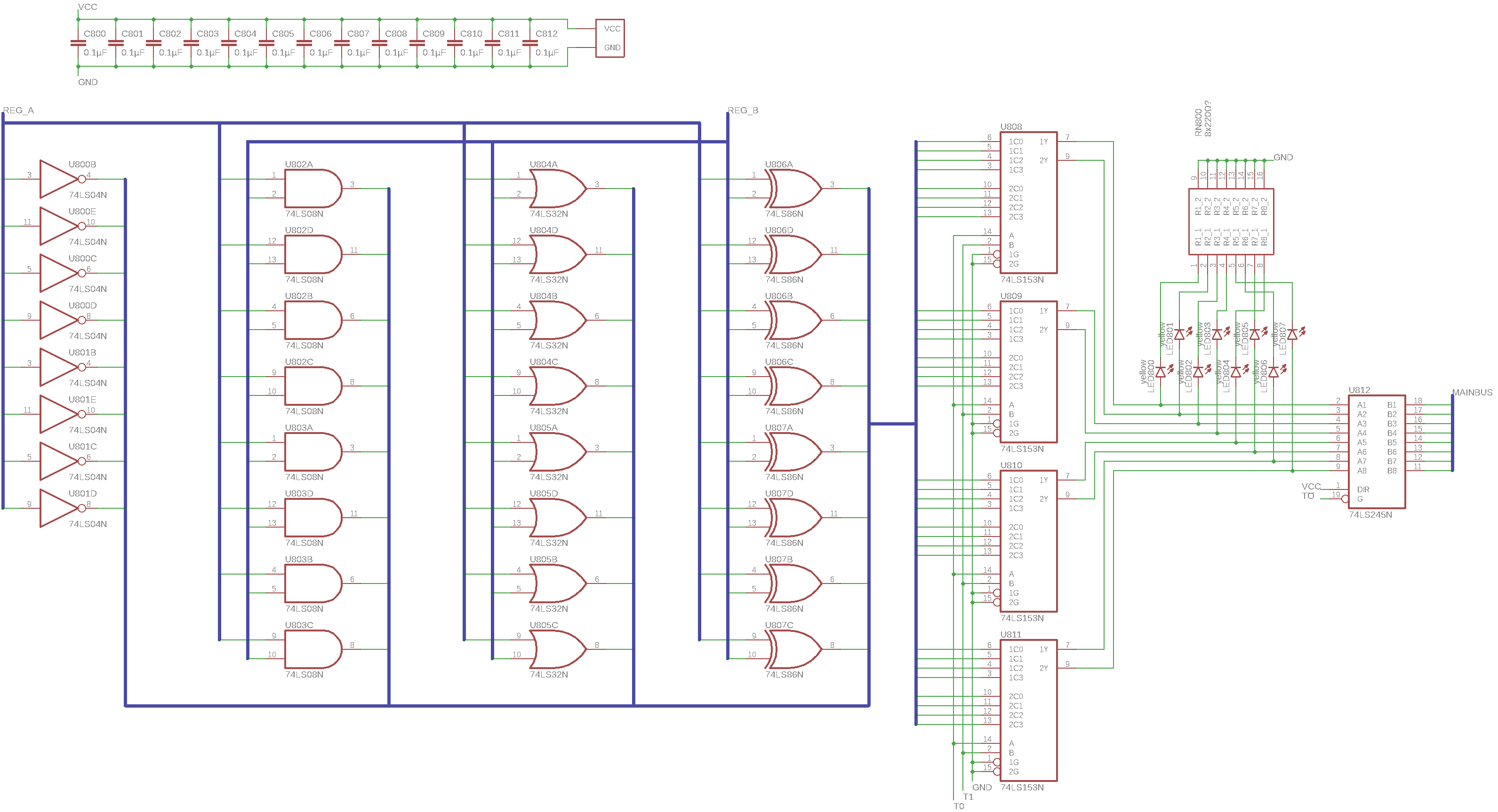
While this page is larger than the previous one, it’s actually a lot simpler. It implements bitwise NOT, AND, OR and XOR operations that can be applied to the registers A and B, which can be quite useful for programming and conditional logic.
The components are straightforward: There are 8 logic gates of each kind named above, used to compute all four operations (NOT A, A AND B, A OR B, A XOR B). To the right there are four dual 4-to-1 selectors (74LS153, just like in the comparator above). They are used to select one of the four results that should be output to the bus. The selected value is then displayed on an LED pack and connected to a bus transceiver for output.
This module together with the arithmetic unit above form the ALU (Arithmetic Logic Unit) of the computer, which does most of the useful work in most programs.
Continued in Part 4.